Data Industrial
Plastic Tee Type Flow Sensor
Manual
5
Page 1: ...le so there is no need for recalibration after servicing or replacement Electronic Types Data Industrial provides several basic sensor configurations using the same impeller element This allows for a wide range of applications and pipe sizes Sensors are normally supplied with 20 feet of 2 conductor 20 AWG shielded U L type PTLC 105 C cable Optional sensors designated with the prefix IR feature two...
Page 2: ...ons should be followed to ensure maximum system accuracy 1 Choose a location along the pipe where 10 pipe diameters upstream and 5 pipe diameters downstream of the sensor provide no flow disturbance Pipe bends valves other fittings pipe enlargements and reductions should not be present in this length of pipe 2 The preferred location for the sensor around the circumference of a horizontal pipe is o...
Page 3: ...irements are as shown in the Specifications section Refer to Technical Bulletin 81 www dataindustrial com Electrical Installation IR sensors The sensor leads are supplied with watertight caps over the ends 1 DO NOT remove the plastic caps from the sensor leads until ready to splice See Application Note 47 and Technical Bulletin 52 www dataindustrial com 2 Use a twisted pair cable suitable for dire...
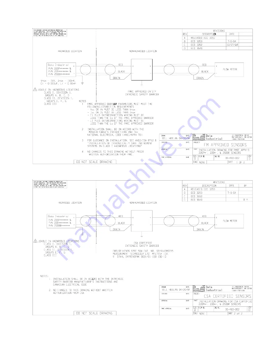
Page 4: ...truments connected to the sensor are each rated either explosion proof or intrinsically safe these devices cannot be installed in a hazardous area The referenced installation drawing shows such apparatus located in a non hazardous location Proper interfacing between the hazardous and non hazardous areas must be provided It is of absolute importance that this interface be constructed and that all w...
Page 5: ...Data Industrial Plastic Tee Type Flow Sensor Manual 5 ...
Page 6: ...n calibrating an output board or when using the raw sensor data as direct output to interface with a device that is not a Data Industrial product Column 5 This column indicates the suggested flow range of each tee sensor Data Industrial sensors will operate both above and below the indicated flow rates However good design practice dictates the use of this range for best performance Sensors should ...
Page 7: ...drop out 6 Inspect the shaft and bearings for wear and replace as necessary 7 Refer to Figure 1 To reinstall position the impeller in the cavity oriented as in Step 4 so that the impeller blades point into the flow direction The flow direction arrow on the top of the sensor housing should point downstream with the impeller blades pointing upstream 8 Carefully push the shaft through the housing and...
Page 8: ...epeatability 0 3 of full scale over recommended design flow range for 228PV Linearity 0 2 of full scale over recommended design flow range for 228PV Transducer Excitation Quiescent current 600uA 8VDC to 35VDC max Quiescent voltage Vhigh Supply Voltage 600uA Supply impedance ON State VLow Max 1 2VDC 40mA current limit 15ohm 0 7VDC Output Frequency 3 2 Hz to 200 Hz for all except 228PF Output Pulse ...
Page 9: ...to the other sensor input terminal Shorting across the sensor input terminals ON and OFF repeatedly allows the display to respond by trying to calculate a flow rate for the frequency of your shorting action If the display does not show a change from 0 00 it indicates a problem with the monitor 3 If the monitor tests ok and there are any splices in the cable break the sensor cable at the splice clo...
Page 10: ...rovided by the Seller and does not cover limited life components such as bearings shafts impellers where wear rate is a function of application and environment Any component not manufactured by the Seller but included in its products shall not be covered by this warranty and is sold only under such warranty as the manufacturer may provide IfBuyerorPurchaserwishestomakeaclaimhereunder heshallsendwr...