Installation
58
System Hardware Guide
c.
Slide the system into the rails that are in the rack. The plastic front bezel on the system
easily pops off.
Do not carry a system
by holding the plastic bezel.
Always move a
system by holding on to the chassis.
d.
Remove the thin, clear plastic wrap that covers the top panel of the system and the clear
plastic tape that covers the top and bottom surfaces of the trim around the front of the
chassis.
e.
Slide the system all the way into the rack.
3.
Determine whether your configuration and ongoing administration access for the system is to
be through an Ethernet connection, a serial console, or a monitor and keyboard.
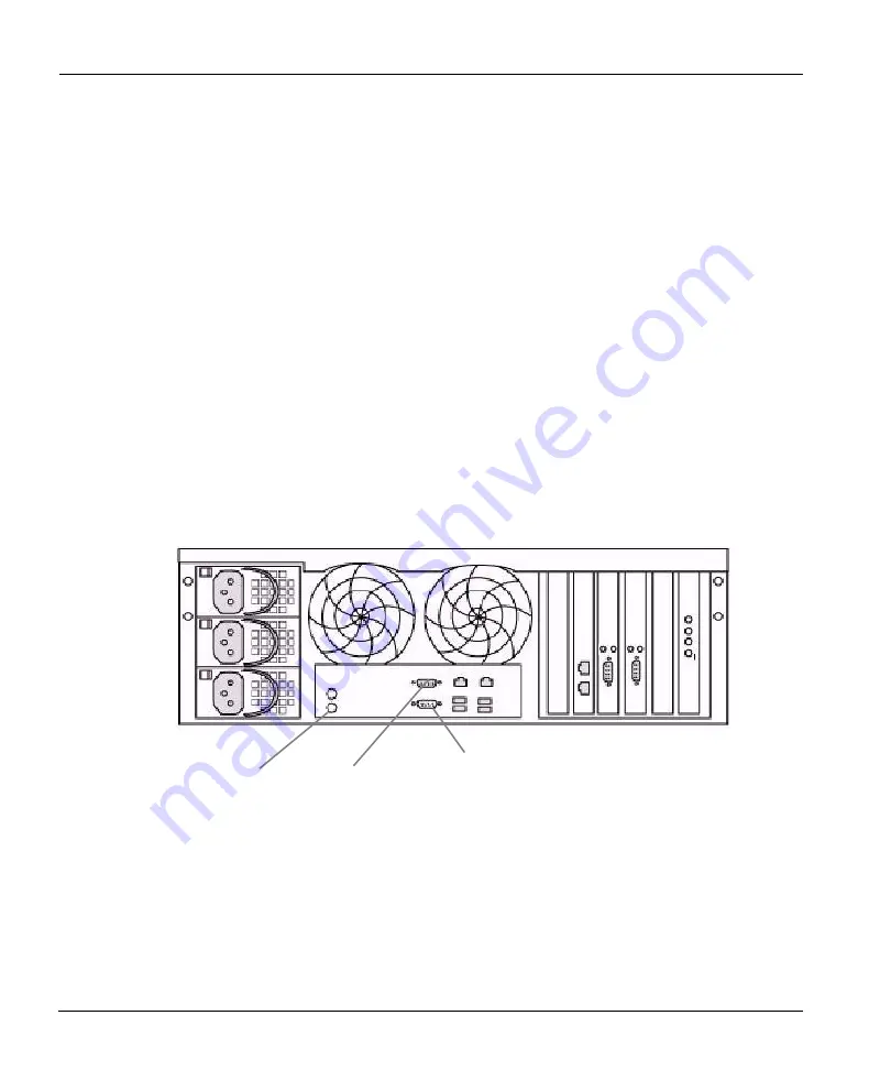
Figure 21: Access points
Console port
Monitor (VGA) port
Keyboard port
-
For an Ethernet connection, attach an Ethernet cable to one of the Ethernet interfaces,
eth0, eth1, or if available, eth2, eth3, eth4 or eth5 on the back panel. See Figure 22 on
page 59 for Ethernet interface locations.
-
For a serial console, attach an RS232 null modem cable to the DB9 port (labeled “Console
Port”) on the back panel. See Figure 21. Use the console communication settings of: 9600
baud, 8 data bits, no parity, 1 stop bit.
-
For a monitor and keyboard, attach the monitor to the port labeled VGA and the keyboard
to the port nearest the keyboard icon. See Figure 21 for locations.
4.
For backup and restore communications to and from the system, attach at least one Ethernet
cable to an Ethernet interface or a Fibre Channel cable to a VTL HBA port on the back panel.
See “System Card Interface” on page 52 for interface locations.


