background image

dCS Vivaldi DAC

 User Manual 

Software Issue 1.0x 


August 2012 


Filename: Vivaldi DAC Manual v1_0x.docx 

Page 16

 English 

version

The Vivaldi Master Clock has 2 Groups of outputs, each of which can be set to any of 6 standard clock 
frequencies. The DAC and Upsampler have 3 and 2 Word Clock inputs respectively, to ensure they 
can have access to a suitable clock despite changing sample rates in the system.  

 Set 

Master 

Clock 

Freq1

 to 

44.1kHz

 and 

Freq2

 to 

48kHz

.  

  Connect one of the 

Clock Group 1

 outputs (44.1kHz) to the 

Word Clock Input

 of the Transport – 

it will automatically sync. 

  Connect one of the 

Clock Group 1

 outputs (44.1kHz) to the DAC’s 

Word Clock In1

 input and one 

of the 

Clock Group 2

 outputs (48kHz) to the DAC’s 

Word Clock In2

 input.  

  Connect one of the 

Clock Group 1

 outputs (44.1kHz) to the Upsampler’s 

Word Clock In1

 input 

and one of the 

Clock Group 2

 outputs (48kHz) to the Upsampler’s 

Word Clock In2

 input. 

  Set the DAC and Upsampler 

Sync Mode

 menu pages to 

Auto

. Remember that this must be set 

separately for each active input. 

  Connect the Upsampler’s 

AES1+2

 outputs to the DAC’s 

AES1+2

 inputs.  

  Connect the Transport’s 

AES1+2

 outputs to the DAC’s 

AES3+4

 inputs.  

  Computer audio sources as required can be connected to the Upsampler’s Asynchronous USB 

interfaces and a NAS drive may be connected via a router to the Upsampler’s Network input (also 
Asynchronous). Please see the Upsampler manual for more information. 


Summary of Contents for DCS VIVALDI DAC

Page 1: ...form or by any means electronic mechanical photocopying recording or otherwise without the prior written permission of dCS1 Any person who does any unauthorised act in relation to this publication may be liable to criminal prosecution and civil claims for damages Information contained in this manual is subject to change without notice and whilst it is checked for accuracy no liabilities can be acc...

Page 2: ...dCS Vivaldi DAC User Manual Software Issue 1 0x August 2012 Filename Vivaldi DAC Manual v1_0x docx Page 2 English version ...

Page 3: ...ogue Outputs 12 STEP 4 Setting the Output Level 12 STEP 5 Choosing a Sync Mode 13 Using the DAC in Master Mode 13 Using a Master Clock in a CD SACD system 14 A full Vivaldi system 15 Advanced options 17 Customising the input configuration 17 Front Panel 18 Remote Control Receiver 18 Display 18 Power Button 19 Menu Button 19 Filter Button 19 Input button 20 Mute Button 20 Rotary Control 20 Rear Pan...

Page 4: ...possible future use If this is not possible replacement packaging can be ordered from dCS or our distributors Details can be found on our web site at www dcsltd co uk A programmable Nevo Q50 colour touch screen remote control configured for Vivaldi is available as an optional extra Positioning the unit For best sound quality the units in the Vivaldi range are designed to be mounted on separate she...

Page 5: ...mains supply The unit s voltage setting is shown on the serial number label If this does not match your local supply voltage DO NOT attempt to use the unit Contact your dealer to have the unit reset Using the unit with the wrong mains setting for your local supply may result in serious damage to the unit and will invalidate the warranty Do not attempt to reset the voltage yourself We do not recomm...

Page 6: ...optic cables for the USB interface use a standard USB2 0 cable fitted with one type A and one type B connector The internal screen must be connected at both ends For analogue outputs use with screened cables of the correct type for balanced outputs use screened twisted pair cables fitted with one male XLR connector and one female XLR connector for unbalanced outputs use coax cables fitted with RCA...

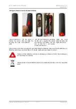
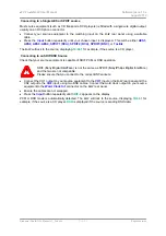
Page 7: ...e spring and pressing the battery into the slot so that the end makes contact with the stud Slide the back plate into place and tighten the screw If the remote control does not appear to work after fitting the batteries make sure that the batteries are fitted the correct way as shown above If in doubt please ask your dealer for advice Failure to fit the batteries correctly can damage your Remote C...

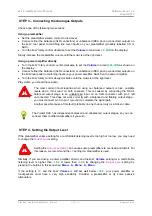
Page 8: ...on and is set up correctly Connect the AES1 or AES A output on your source equipment to the AES1 input on the DAC rear panel and the AES2 or AES B output to the AES2 input using two XLR cables Ensure the cables are not swapped Press the Input button repeatedly until AES1 2 is displayed Analogue outputs To Amplifier Figure 1 Using the Vivaldi Transport with the DAC The DAC will lock to the source d...

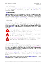
Page 9: ...a CD player Connecting to an SDIF DSD Source Check that your source equipment is capable of SDIF PCM or DSD operation SDIF Sony Digital InterFace is not the same as SPDIF Sony Philips Digital InterFace and the two are not compatible Please ensure that you connect to the correct BNC sockets Connect the CH1 output on your source equipment to the CH1 input on the DAC rear panel and the CH2 output to ...

Page 10: ...nd then use the Menu button to select the Class 1 icon Wait 10 seconds while the Class 1 code is loaded USB Audio Class 2 The interface operates at up to 192kS s including DSD over PCM For Mac OSX version 10 6 3 or later is required For Windows 7 or Vista or XP the driver files on the dCS USB Class 2 Driver disc supplied must be installed onto the computer before use see page 10 To select Class 2 ...

Page 11: ...program processes the audio One particular problem that has been identified concerns iTunes when running on Windows systems The default output word length is 16 bits and must be changed to 24 bits for correct operation To do this click on Start Control Panel Quicktime Click on the Audio tab of the Quicktime panel and select 24 bit in the Size field of the Sound Out section Selecting the Vivaldi DA...

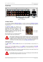
Page 12: ...outputs is hiss unstable levels and a thin sound on both channels This is caused by connecting the DAC s balanced output stage to an unbalanced input on an XLR connector with pin 3 left unconnected This does not work correctly with a balanced and floating output stage you must connect pin 3 to pin 1 ground to complete the signal path Another possible cause of this fault probably on one channel onl...

Page 13: ... must be set separately for each input that is used This arrangement is necessary to allow a mixture of clocked and un clocked sources to be used in the same system Using the DAC in Master Mode You can use Master Mode with the PCM inputs ONLY if your source equipment can lock to a 44 1kHz word clock and the DAC is receiving data at 44 1 88 2 176 4 or 352 8kS s or DSD If the system is not set up co...

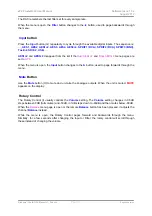
Page 14: ...p 1 Outputs to the Word Clock Inputs of the Transport and DAC Use the Clock s Freq1 button to set the Group 1 Outputs to 44 1kHz to suit the CD Transport To sync the DAC to Word Clock 1 open the menu navigate to the Settings Sync Mode menu page The button sequence is Menu Menu and then use the Menu button to select the Word Clock 1 icon The system will re lock and un mute Please consult the Vivald...

Page 15: ... audio files with different sample rates or using an Upsampler with a variety of output sample rates Analogue outputs to Amplifier Figure 5 A 4 box Vivaldi system plus computer audio sources The system shown above makes excellent use of the Vivaldi s facilities The Upsampler can be sourced from the Transport a PC a NAS drive an iPod Phone Pad or a USB flash drive The multiple clock connections sho...

Page 16: ...1 outputs 44 1kHz to the DAC s Word Clock In1 input and one of the Clock Group 2 outputs 48kHz to the DAC s Word Clock In2 input Connect one of the Clock Group 1 outputs 44 1kHz to the Upsampler s Word Clock In1 input and one of the Clock Group 2 outputs 48kHz to the Upsampler s Word Clock In2 input Set the DAC and Upsampler Sync Mode menu pages to Auto Remember that this must be set separately fo...

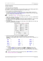
Page 17: ...to Start Control Panel Hardware and Sound Devices and Printers Find the Port that is connected to the unit or the USB adapter and note the COM port number e g COM4 Run ttermpro exe Click Setup Serial Port set the panel as shown below set the Port field to the COM port number you identified earlier and click OK In the Tera Term window type the command NAME n newname where n is the number correspond...

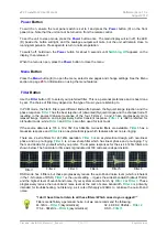
Page 18: ...tus the data format Some examples are No Input 16 44 1 the number of active bits and the sample rate 24 192 DSD or MUTE Between tracks on a CD the number of active bits is zero so 0 44 1 may be displayed The icons at the bottom left corner are the selected Filter Filter 1 is shown and the Sync mode slave to Audio is shown Other icons such as Phase Invert or Channel Swap appear here when required T...

Page 19: ...progressively more relaxed image rejection and progressively better transient response Filter 2 is often preferred for orchestral music while Filter 3 and Filter 4 are often used for rock music If the source data rate is 176 4 192 352 8 or 384kS s two extra filters are available Filter 5 has a Gaussian response and Filter 6 is an asymmetrical type which features almost no pre ringing There are 2 e...

Page 20: ... to OFF When the menu is open the Input button changes to the button used to page forwards through the menu Mute Button Use the Mute button H to mute and un mute the analogue outputs When the unit is muted MUTE appears on the display Rotary Control The Rotary Control I usually controls the Volume setting The Volume setting changes in 0 5dB steps between 0dB full volume and 50dB in 1dB steps down t...

Page 21: ...ufacturers provide unbalanced inputs on XLR connectors by leaving pin 3 floating This arrangement does not work correctly with a floating output stage resulting in extra noise unstable signal levels and a thin sound If you want to use the Vivaldi DAC with this type of input link pin 3 to pin 1 in the cable at the amplifier end In such cases we recommend that you use the Unbalanced Outputs instead ...

Page 22: ...ral common formats running on Windows 7 Windows Vista SP2 Windows XP SP3 and Apple Mac OSX 10 5 10 6 with various PCM streaming programs but we cannot accept responsibility for correct operation with all source devices operating systems or software The USB interface is designed to work with a computer or sound server Nothing useful will happen if you connect the interface directly to an MP3 player...

Page 23: ...to remotely control the unit during automated production testing at dCS Text mode is for use with a household automation system If you would like to use this mode please download the list of remote control commands from www dcsltd co uk page support The interface is designed to be used with a straight through cable wired pin 1 to pin 1 etc The pin connections are Pin 2 dCS unit transmit Pin 3 dCS ...

Page 24: ...he DAC s outputs off and on The Program and Clear buttons are used with the 0 9 buttons to set or change the Transport s track sequence for the loaded disc The 0 9 buttons select the current track to be played by the Transport Pressing 5 or 05 will select track 5 The Stop Eject Play Pause Previous Track Next Track Jog Back and Jog Forward buttons operate in the same way as those on the Transport f...

Page 25: ... AES operation Enables Dual AES operation Changes the output phase for both channels Reverse the Left and Right outputs Factory Reset Reset Names RS232 Mode USB Class Balance Restores standard factory settings Resets the user selected input names to standard Select RS232 Text Mode or Binary Mode Selects USB Class 1 24 96 or Class 2 24 192 Allows Balance adjustment by rotary control Display Setting...

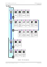
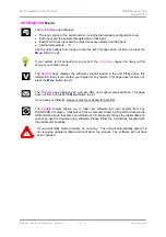
Page 26: ...menu page Each unit in the range has either three or four top level menu pages The INFORMATION menu gives unit set up details software issues serial number and contact details Each model has a different SETTINGS menu which allows you to set some features that are not directly accessible from the front panel The DISPLAY SETTINGS menu is used to adjust the display The SIGNAL GENERATOR menu featured ...

Page 27: ...nit Please have this information ready if you contact your dealer for any reason This page does not time out press the Menu button to exit The Contact page displays dCS web site URL and support email address This page does not time out press the Menu button to exit If you have any difficulty please contact your dealer for help first The Update feature allows you to load new software into your syst...

Page 28: ...e set to Master mode unless the DAC is locked to a 44 1 or 88 2kHz word clock connected to Word Clock In1 Auto This mode is designed for easy operation with a Vivaldi Clock Upsampler and computer where the data rate may keep changing Connect the Word Clock In1 input to a Clock output set to 44 1 or 88 2 or 176 4kHz and connect the Word Clock In2 input to a Clock output set to 48 96 or 192kHz The U...

Page 29: ... errors on recorded music Channel Swap swaps the channels from normal to swapped to correct a connection error Correct the error and change back to normal Channel Swap does not affect the Channel Check feature Balance the operation of the rotary control changes to adjust the balance Each channel can be varied from 0dB to 6dB in 0 1dB steps then mute below that Balance adjustment ends after this me...

Page 30: ...es all inputs for use After a reset the special set up information is lost Factory Reset resets the unit to standard settings These are Volume to 30dB Balance to centre Input to AES1 Sync to Audio for all inputs except USB sync to Master SDIF sync to Word Clock In1 Filter to 1 for all sample rates Phase to Normal Channel Swap to Normal Dual AES1 2 3 4 to Auto Output Level to 2V Display to On Brigh...

Page 31: ...eft and right channels are swapped somewhere in your system This test is not affected by the Channel Swap menu page setting Phase Check runs a routine to test the system for phase reversals Noise is output in phase on both channels while the display shows In Phase Press the Menu button the noise on the right channel is inverted while the display shows Out of Phase The first burst should produce a ...

Page 32: ...iver required 44 1 48 88 2 96 176 4 or 192kS s when set to Class 2 no special driver is required for OSX 10 6 onwards load the dCS USB Class 2 driver for Windows In Class 2 decodes DSD in DoP format The USB interface operates in true asynchronous USB mode Clocking 3x Word Clock Inputs on 3x BNC connector accept standard word clock at 32 44 1 48 88 2 96 176 4 or 192kHz The data rate can be the same...

Page 33: ...0kΩ load is recommended Unbalanced outputs 1 stereo pair on 2x RCA Phono connectors Output impedance is 52Ω maximum load is 600Ω a 10kΩ 100kΩ load is recommended Size and weight 444mm 17 5 long x 435mm 17 2 deep x 151mm 6 0 high Allow extra depth for cable connectors Allow space for air flow around the unit 16 2kg 35 65lbs Power requirements Internally set to either 100 115 120 220 or 230 240V AC ...

Page 34: ... damage to the unit risk of fire or electric shock and will invalidate the warranty Fuse failure is rare Referring to the diagram below remove the power cable insert small flat bladed screwdrivers into each fuse holder slot A push them together to release the clips and pull the fuse holder out Pull out the blown fuse and fit a new fuse in the holder B Orient the fuse holder as shown C and push the...

Page 35: ...epairs are carried out the product is not used in accordance with the Operating Conditions stated in this manual the product is serviced or repaired other than by dCS or our authorised service agents the product is operated without a mains earth or ground connection the unit is returned inadequately packed dCS reserve the right to apply a service charge if a product returned for warranty repair is...

Page 36: ... FPGAs and DSPs This gives us the ability to update our products to add extra features update digital interface standards or make performance improvements by loading new software Occasionally a hardware upgrade may be necessary also to increase the capacity of the electronics add extra connectors or extra front panel controls Please note that not all software updates produce an audible improvement...

Reviews: