

SELECT
ENTER
Program card
Specification
Radio & ESC set-up
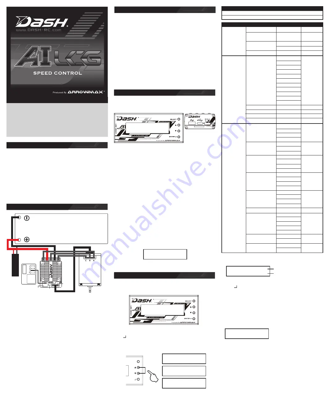
Installation & Connectors
*** 32 bit processor
*** Low resistance FET
*** Continuous current
*** Auto Fan control
System:
Brushless
Forward/Brake/Reverse:
Yes (Factory preset at Forward/Brake)
Dimensions:
35.8(L) x 29.5(W) x 13.85(H)mm
Weight:
27g (excluding wires)
Voltage Input:
(4.8 – 8.7V DC)
6 Cells NiCD/NiMH
2-Cell LiPO / 2-3 Cell LiFe
Continuous Current:
100A
Maximum Current:
400A
Motor Limit:
Over 10.5 Turns
Motor Type:
Sensored 540 sized brushless motors
B.E.C. Output:
6V / 7A / 3A
Multi Protection System:
Yes
• Position the ESC where it is protected in the event of a crash. Use the supplied
double sided tape to secure the ESC to the chassis.
• Install/Solder the relevant battery connector (Battery Specific) to the battery
wires. RED to +ve and BLACK to –ve. (
WARNING!
Reversing the battery polarity
will destroy your ESC and void the warranty.)
• Connect supplied BEC wire(180mm) to 3pin port match the ”- + s” between the
receiver connector and ESC.
• Connect supplied Switch wire to 2pin port (- o).
• Connect the 3 motor wires to the motor; you can either solder the wires directly
to the motor or use your favorite connectors. Match the label of the ESC Output
(A, B, C) to the Tab labels on the motor when soldering. Avoid soldering each
joint for longer than 5 seconds. Prior to operation make sure you have not
created a short by either creating a wire bridge or solder bridge on the solder tabs
on the motor. (
WARNING!
Improper wiring may damage the ESC and void the
warranty.)
• Connect the sensor cable between the ESC sensor plug and the Motor sensor
plug.
• Connect the receiver plug to the CH2/throttle pin of the receiver.
• Secure the on/off switch in a place where it will not be accidentally knocked to the
“off” position during a crash.
• The Fan port voltage is drawn directly from the battery.
• The Motor configuration A-B-C can be changed to C-B-A in the Initial Setup
section of the Program Card. Ensure that your physical wiring configuration of
A-B-C match the Initial Setup options of the Program Card. (
WARNING!
Improper configuration may damage the ESC.)
Customizing the ESC
Operation
Transmitter Settings:
Throttle Travel
Maximum / 100%
Brake Travel
Maximum / 100%
Throttle Exponential
Start with 0%
Throttle Neutral Trim
Center / 0
Throttle Servo Reverse
Reverse (Futaba, KO, Sanwa)
Initial set-up of the throttle end-points of the ESC:
• Connect the power wires of the ESC to a fully charged battery set; making sure
the polarity is correct.
• Bind your receiver and transmitter first if your radio requires you to do so.
• Turn on the transmitter and hold the throttle at full brake position.
• Turn on ESC and listen for 2 beeps.
• After you hear the 2 beeps, apply full throttle and listen for another 2 beeps.
• Once you hear the 2 beeps, release the throttle to neutral position.
• A beep will then sound, signifying that the ESC endpoints have been
successfully set.
Note!
If you do not hear the beeping sound as described above, try reversing
the throttle reverse setting in the transmitter.
Due to the different requirements of each style and class of racing, it is important to
customize your ESC for each use case. Customization of the ESC is done using the
Program Card (Sold Separately):
To begin, connect the battery wires to a charged battery, then connect supplied 4pin
wire (100mm) to the ESC setting port (4pin port) and Program Card. Turn on the
ESC and the Program Card will activate automatically. Note that the screen will
show “Loading…” during initialization – indicating that the ESC is copying the
current setup in the ESC to the Program Card. Once loading is completed, the
screen will show “DASH AI LCG” and "Program". You can now begin programming
your ESC.
Press “Enter” to access Program, Update or Data Record.
TIPS!
Whenever in doubt, double check your ESC setting by initializing the
Program Card again and checking each menu setting.
Navigation around the Program Menu is done using the 4 buttons on the right hand
side of the Program Card. The function of each button varies depending on which
screen the display is showing:
"Select" button------------------------go to next select
Press and Hold "Select" button two second -------go to back page
“
▲
” button
- Scroll up
“
▼
” button
- Scroll down
“Enter” button
- Send Changes from Program Card to the ESC
and overwrite old data in the ESC
NOTE!
The Program Card is not included and is sold separately.
The Program Card will compare the Parameters within the card and ESC before
sending. If changes are detected, you will hear a series of beeps and the Program
Card will display:
Send Success
TIPS!
Do not worry about making mistakes. You will not damage the ESC during
setting. If in doubt, you can always reload the default set up and start over again.
Getting started
Turn on the on/off switch, the screen will display:
DASH AI LCG
1: Program
DASH AI LCG
3: Data Record
DASH AI LCG
2: Update
DASH AI LCG
1: Program
BLINKY MODE
1: Quick Setup
Use “
▲
” button and “
▼
” button to find [Program], [Update] or [Data Record].
Press “ ” button to choose. Each mode presented are independent from each
other and will require setup.
Press “SELECT” button for 2 seconds to go back to the previous screen.
1. Program
2. Update
Use “SELECT” button to find
[BLINKY MODE].
Use “
▲
” button and “
▼
” button to
find the right position of the motor
link.
Press “ ” button to set up your ESC after you choose the right motor link.
Updating of ESC Firmware:
Scroll to the “Update” menu and press “Enter”. This will show the current ESC
FW Version. Press “Enter” again to access the SD cards Firmware folder. Select
the FW Version that you would like to use to update the ESC. Press “Enter”
again and the update will commence (It will take around 1 minute to complete the
update).
Instruction Manual
Please check the
connections.
Thank you for choosing Dash Products. Welcome to the power and
convenience of Brushless RC. By purchasing the AI LCG Competition
Brushless Electronic Speed Control (“ESC”) you have chosen one of the
most advanced speed controls in RC Racing. The AI LCG allows
customization for multiple programmable parameters (using the ESC’s
Program Card which can be purchased separately). Please read this
manual thoroughly to familiarize yourself with the installation, setup and
operation. By operating this product, you accept the Dash Warranty Terms.
Blinky Mode
1.Torque Feel
Level:1-15
15
2.Pulse Width
2000-32000Hz
8000HZ
Quick Setup
Modulation (PWM)
3.DragBrake
OFF
OFF
1%-30%
4.Compress
0%-50%
10%
-5
-4
-3
-2
-1
1.TorqueFineTune
Normal
Normal
+1
Advance Setup
+2
+3
+4
+5
2.BrakeFreq
800-5000Hz
800
3.InitialBrake
0-60%
60%
4.Initial Brake range
0-100%
50%
5.MaxbrakeForce
0-100%
100%
Forward/Brake
1.RunningMode
Forward/Rev
Forward/Brake
For/Brake/Rev
For/Hold/Rev
LiPolymer
2.Battery (Type)
LI-FE
LiPolymer
NI-XX
OFF
3.CutOffVolage
LOW
OFF
MIDDLE
HIGH
95°
4.EscOverHeat
105°
120°
120°
No Protection
Initial Setup
95°
5.MotorOverHeat
105°
120°
120°
No Protection
6.NeutralRange
2%-15%
5%
Auto
40%
7.Fan Mode
60%
Auto
80%
100%
8.BEC Voltage
6V
7V
7V
9.Motor Direction
CCW
CCW
CW
1. Program
A + B – C
C + B – A
Preparing the SD card for use:
Format a microSD card using FAT32 file structure using a personal computer. If
you are using a Micro SD Card larger than 32GB, you will need to use a 3rd
party SW Package to do this. Create a new folder called “Firmware”. Download
the latest firmware from www.dash-rc.com and copy the file to the “Firmware”
folder on the Micro SD card. Once completed, install the MicroSD card into the
microSD card slot of the Program Card. Both the Program Card and ESC FW
DASH AI LCG
21.10.180508A
Updating of Program Card Firmware:
Depress and hold the Program card’s “Enter” button while turning on the ESC. It
will display the current Program card FW Version. Press “Enter” again to access
the SD cards Firmware folder. Select the FW Version that you would like to use
to update the Program Card. Press “Enter” again and the update will commence
(It will take around 1 minute to complete the update).
RECEIVER
CAPACITOR
BATTERY
CH1
CH2
CH3
BAT
Setting port
for program
card
Fan port
On/Off
switch
+ RED
– BLACK
SENSOR WIRES
BLACK. A
BLACK. B
BLACK. C