background image


eCard-FRM11 User’s Manual (Rev 2.1) 


                                                                  -

10

-                                                      http://www.daqsystem.com 

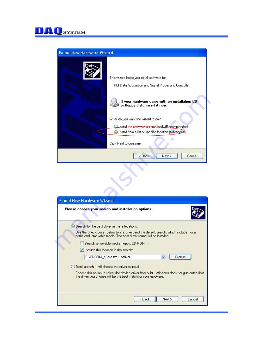
The Add new Hardware Wizard will install the driver in the following process.   


If new hardware is found, Wizard will ask you to install the corresponding driver. For installation   

of the driver, select the item “Install from a list or specific location (Advanced)” and click “Next”   

as in the figure. 


Summary of Contents for eCard-FRM11

Page 1: ...y DAQ system is believed to be accurate and reliable However no responsibility is assumed by DAQ system for its use nor for any infringements of patents or other rights of third parties which may resu...

Page 2: ...escription 3 1 PCB Layout 3 2 Description of the Functional Blocks 3 3 Connector Pin out 4 Installation 4 1 Package content 4 2 Installation Sequence 5 Sample Program 5 1 FrmTest 5 2 FrameView 6 Test...

Page 3: ...eceived image frame data to the system via Express Card transmitting receiving UART data and controlling CC Camera Control signal Figure 1 1 eCard FRM11 board Usage Figure 1 1 shows the eCard FRM11 is...

Page 4: ...PCI Target Master PCI BUS Local Bus Address Data Mem I O Reserved 0x00 0x5F Reserved 0x70 0xAF UART 0x60 Camera Link LVDS 0xC0 Interrupt controller DIO 0xD0 Ext Address Data Control Local BUS Interru...

Page 5: ...acquisition UART communication 8 bit data 1 start 1 stop No parity 9600bps 4 bit CC Camera Control output Windows 2000 SP4 or Windows XP SP1 above Convenient Windows Application Programming Interface...

Page 6: ...n 3 1 PCB Layout Figure 3 1 eCard FRM11 PCB Layout 3 2 Description of the Functional Blocks 1 FPGA All of the board functions are controlled by the Logic program of the FPGA 2 LVDS Receive Image frame...

Page 7: ...nd information 3 10 9 8 7 6 1 2 5 4 19 18 17 16 15 14 13 12 11 24 23 22 21 20 Inner shield Inner shield 26 25 SerTFG SerTC Xclk X3 X2 X1 X0 Inner shield Frame Grabber SerTFG SerTC Xclk X3 X2 X1 X0 Inn...

Page 8: ...9 SerTFG Serial to Frame grabber 20 SerTC Serial to Camera 21 X3 Camera link LVDS receive data3 22 Xclk Camera link LVDS receive clock 23 X2 Camera link LVDS receive data2 24 X1 Camera link LVDS recei...

Page 9: ...1 Package contents In addition to the user s Manual the package includes the following items If any of these items is missing or damaged contact DAQ system eCard FRM11 board CDROM drivers manual API...

Page 10: ...ardware Wizard will install the driver in the following process If new hardware is found Wizard will ask you to install the corresponding driver For installation of the driver select the item Install...

Page 11: ...eCard FRM11 User s Manual Rev 2 1 11 http www daqsystem com...

Page 12: ...mpletely finished you confirm it in the following ways Do the following steps to show up the Device Manager window My Computer properties Hardware Device Manager Multifunction Adaptors PCIe FRM11 Figu...

Page 13: ...w If you can see the PCIe FRM11 The eCard FRM11 uses a same driver with PCIe FRM11 because of compatibility at Multifunction Adaptors the driver installation is to have been over Check the red circle...

Page 14: ...frame data to memory or hard disk and displays it to Hexa decimal values which can utilize necessary frame data to developers The other is FrameView exe It is easy to understand frame data to display...

Page 15: ...board 2 Start button Press this button to begin to save image data from Camera Link 3 FRAME Read button Press this button to read the image frame data of the board to your PC If image frame data is no...

Page 16: ...to the board 7 UART Close button Press this button to finish usage of the board and terminate the program 5 2 FrameView Figure 5 2 When Sample program FrameView exe is executed To run the sample appl...

Page 17: ...execute FrameView exe The image that is looked to a monitor as it accesses a Camera link camera to eCard FRM11 board 1 Select resolution Display resolution Select it as fitted to input resolution Rev...

Page 18: ...the ECard FRM11 is shown outside the PC in this figure but actually it is located in a PCI slot inside the PC At this connected state turn the all power on and execute test program FrmTest exe on the...

Page 19: ...r Then the gotten data are displayed on the editor box below the button Step 2 Write the data to the editor box beside the Send Serial Data button and press the Send Serial Data button to send it to t...

Page 20: ...erface Camera Link interface specification Functions 16 24bits Image Frame Acquisition Image Frame Data Transfer to PC 9600bps UART Tx Rx 4 bit CC camera control output Software Supported OS Windows 2...

Page 21: ...Link Interface Standard for Digital Cameras and Frame Grabbers Camera Link committee 2 PCI Local Bus Specification Revision2 1 PCI Special Interest Group 3 How to install PCI DAQ Board DAQ system 4 A...

Reviews: