background image


Installation 


Palladium VPA series II Installation 

Remove all packing materials. Check that all foam and plastic padding has been removed. 
Screw the equipment into a 19" rack. Connect all cables. 

Always disconnect from electric mains power supply before cleaning or servicing. 
Damages caused by non-observance are not subject to warranty. 


Set Up and Operation


Before plugging the unit in, always make sure that the power supply matches the product specification 
voltage. Do not attempt to operate a 120V specification product on 240V power, or vice versa. 
Do not supply power before all components of the system are set up and connected properly. 
 

Low Impedance Speaker Output: 8Ω


The low impedance 8Ω terminal is for connecting of a few large-output speakers, when constant-voltage 
speaker systems are unnecessary or the distance between the amplifier and the speakers is below 50m. 
The total speaker load impedance must be matched to the output impedance (8Ω) of the amplifier for 
the most efficient power-transfer. 
Be sure that total impedance of speakers is above 8Ω however; do not raise the amplifier’s output power 
above the allowable input power of the speaker. If the amplifier’s output power should be raised above 
the maximum, the speakers could be damaged. 
 

 Fig. 4


Connection Input 

The balanced phone jack inputs have a nominal impedance of 20 KΩ (10KΩ with unbalanced wiring) 
and will accept the line level output of most devices. The correct input depends on 2 factors: (1) whether 
the input signals are balanced or unbalanced, and (2) whether the signal source floats or has ground 
reference. 
 

Connecting Power 

The actual current draw, the amplifier demands from the AC mains, depends on many factors (its load, 
output level or the crest factor of its program material).  
The power requirement is rated under typical music conditions, with both channels driven so those peaks 
are just at the clipping point. 
 

Summary of Contents for VPA-060

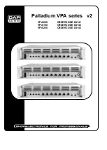
Page 1: ...Palladium VPA series v2 VPA 060 ORDERCODE D4141 VPA 150 ORDERCODE D4142 VPA 250 ORDERCODE D4143...

Page 2: ...AP Audio for more excellent audio products We design and manufacture professional audio equipment for the entertainment industry New products are being launched regularly We work hard to keep you our...

Page 3: ...PA series Product Guide Warning Unpacking Instructions Safety instructions Operating Determinations Return Procedure Claims Description Features Frontside Backside Installation Set Up and Operation Co...

Page 4: ...ation and maintenance of this system has to be qualified follow the instructions of this manual Before you initial start up please make sure that there is no damage caused by transportation Should the...

Page 5: ...cord or signal cable or select the input mode switch Extreme frequency boosts in connection with a high input signal level may lead to overdriving your equipment Should this occur it is necessary to...

Page 6: ...od to use Note If you are given an RMA number please include the following information on a piece of paper inside the box 1 Your name 2 Your address 3 Your phone number 4 A brief description of the sy...

Page 7: ...1 Control 2 CLIP SIGNAL POWER LEDs 9 Mic 2 Control 3 Z1 Z2 Z3 Z4 Switches LEDs 10 Mic 1 Control 4 M Volume Control 11 Mic 2 Input Jack 5 Treble Control 12 Mic 1 Input Jack 6 Bass Control 13 Chime Res...

Page 8: ...and the speakers is below 50m The total speaker load impedance must be matched to the output impedance 8 of the amplifier for the most efficient power transfer Be sure that total impedance of speaker...

Page 9: ...ture range under all normal conditions When a channel s heat sink temperature reaches 90 C which may indicate an obstructed air supply clogged air filter etc the channel will disconnect its load Norma...

Page 10: ...em This gives the advantage of increasing their life and reliability Periodically check your cables A great number of problems faulty contacts ground hum discharges etc are caused entirely by using un...

Page 11: ...d screwdriver into a slot in the fuse cover Gently pry up the fuse cover The fuse will come out 3 Remove the broken fuse If brown or unclear it is burned out 4 Insert the replacement fuse into the hol...

Page 12: ...1 2 66dB Aux 1 2 70dB Tone Bass 10 dB at 100 Hz Treble 10 dB at 10 Hz Muting function Mic 1 overrides other input signals with 0 30dB attenuation Input Connectors 2 x XLR 2 x Jack mounting socket Powe...

Page 13: ...2010 Dap Audio...

Reviews: