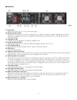
DAPAudio TAS-1100 Manual Download Page 8


Backpanel 


            Fig. 3 


19. Power Fuse. 

      Replace the fuse only by a fuse of the same type. 

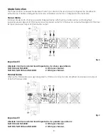
20. Mode Selection Switch.                                                                                                

      This recessed, three-position switch configures the amplifier for Stereo, Parallel or Bridged Mono Mode      
      operation. Amplifiers are factory configured for Stereo Mode. See the section on Mode Selection for    
      more information. 

21. Bridge Mode LED. 

      Indicates that the amplifier is working in bridge mode. 

22. Input Sensitivity Selector. 

      This selector allows you, to choose the input sensitivity: 0,775V, 1,0V or 1,4V. 

23. Air cooling windows 

      Make sure these outlets remain clear to allow unrestricted air flow. 

24. Mains Cord 

      Connect to the mains. 

25. Output terminal Connectors. 

      Using speaker cables, make connections to both the channel A and channel B connectors for Stereo or  
      Parallel mode, use the red terminals only for Bridged mono mode. 

26. Output Speakon Connectors. 

      Use either the speakon connectors or the terminals. Using the speakon connectors, make connections  
      to both the channel A and channel B connectors for Stereo or Parallel mode, use only the channel A  
      connector for Bridged mono mode. Using the terminals, make connections to both the channel A and  
      channel B terminals for Stereo or Parallel mode, In bridged mono mode use only the red terminals. For       
      more information see page 8 and 9. 

27. Grounding Switch. 

      To eliminate groundloops, put the selector in "OFF" position.


28. 30Hz High pass filter select. 

      This switch is used to cut the low frequencies under 30Hz.


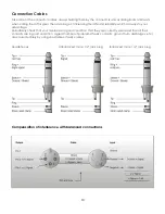
29. Balanced XLR Input Connectors. 

      These connectors accept input signals on XLR input plugs, See the section on connecting cables on  
      page 10/11for information on polarity, Connectors for each channel are in parallel, The unused  
      connectors may be used for linking to other amplifiers. 

30. Balanced Link Out connectors. 

      Used to Link the input signals to other amplifiers. 


Summary of Contents for TAS-1100

Page 1: ...TAS 1100 ORDERCODE D4190...

Page 2: ...ed You can rely on DAP Audio for more excellent audio products We design and manufacture professional audio equipment for the entertainment industry New products are being launched regularly We work h...

Page 3: ...00 TAS4000 Product Guide Warning Safety instructions Operating Determinations Description Features Overview Front panel Overview Back panel Operation Mode selection Connection Cables Maintenance Troub...

Page 4: ...rd and all connections with the mains with particular caution Never remove warning or informative labels from the unit Never use anything to cover the ground contact Do not insert objects into air ven...

Page 5: ...ne amplifier you should use a signal distributor If your Dap Audio device fails to work properly discontinue use immediately Pack the unit securely preferably in the original packing material and retu...

Page 6: ...RMS 2 X 700W TAS 4000 Not allowed RMS 2 X 2000W RMS 2 X 1200W Features Clip limiting Thermal protection VHF protection Short circuit protection DC voltage protection Zero current protection Zero impac...

Page 7: ...me scale indicator This indicator displays the volume attenuation of Channel 2 8 Channel 2 Input Attenuator Use to attenuate the input signal of channel 2 Pressing the control for 2 seconds mutes Chan...

Page 8: ...r Bridged mono mode 26 Output Speakon Connectors Use either the speakon connectors or the terminals Using the speakon connectors make connections to both the channel A and channel B connectors for Ste...

Page 9: ...when ordered DAP audio amplifiers shipped to customers are configured as follows North America 120VAC 60Hz Europe 230VAC 50Hz Asia 220VAC 50Hz 60Hz Australia 240VAC 50Hz South America 120VAC 60Hz or 2...

Page 10: ...ces output at Channel A s output while signal at Channel B s input produces output at Channel B s output Fig 4 Important Absolute minimum nominal load Impedance for stereo operation Is TAS1100 and TAS...

Page 11: ...input may be used Use extreme caution when operating the amplifier In Bridged Mono Mode Never ground either side of the speaker cable when the amplifier Is in Bridged Mono Mode both sides are hot If a...

Page 12: ...s always to your advantage Periodically check that your cables are in good condition that they are correctly wired and that all their contacts are in good condition a great number of problems faulty c...

Page 13: ...n the fuse cover Gently pry up the fuse cover The fuse will come out 3 Remove the broken fuse If brown or unclear it is burned out 4 Insert the replacement fuse into the holder where the old fuse was...

Page 14: ...05 0 05 0 05 Slew rate 20V s 20V s 20V s 20V s 20V s Damping factor 300 300 300 300 300 S N Ratio 80dB 80dB 80dB 80dB 80dB Sensitivity Voltage gain 36 6dB 39dB 40dB 41 2dB 42dB Input impedance Output...

Page 15: ...13 TAS Block Diagram...

Page 16: ...1 16 2 3 4 5 1 5 0 58 1 16 2 3 2 5 0 35 0 7 1 39 4 0 22 0 44 0 87 5 0 5 4 3 8 2 15 5 0 75 2 9 5 6 10 8 1 5 1 45 2 9 5 6 2 5 0 87 1 74 3 4 4 0 55 1 09 2 2 6 0 37 0 73 1 45 10 0 5 8 24 15 5 28 0 75 5 6...

Page 17: ...load 5 18 0 81 1 61 3 2 16 0 51 1 02 2 14 0 32 0 64 1 28 12 0 2 0 4 0 8 10 0 128 0 25 0 51 10 18 1 61 3 2 6 2 16 1 02 2 4 14 0 64 1 28 2 5 12 0 4 0 8 1 6 10 0 25 0 51 1 01 40 18 6 2 11 9 22 16 4 7 7 1...

Page 18: ...2007 DapAudio...

Reviews: