8
Switches and controls
AC-Power-Switch-Circuit-Breaker
Never try to hold the switch in the „ON“-position, if it won’t stay there by itself.
The amplifier has a combined AC-switch/Circuit-Breaker on the front panel. If the switch shuts off during
normal use, push back to the ON position once. If it will not stay on, the amplifier needs servicing switches
and controls.
Input Attenuator
Whenever possible, set attenuates fully clockwise to maintain optimum system headroom. The input
attenuator controls (one for channel A, one for channel B) located at the front panel adjust gain for their,
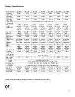
respective amplifier channels in all modes. See the specifications at the end of this manual for standard
voltage gain and input sensitivity information. When operating the amplifier in bridged mode, both attenuates
must be in the same position, so the speaker load will be equally shared between the channels.
Mode-Select-Switch
The rear panel mode select switch determines whether the amplifier is in the stereo or bridged mono mode.
Do not operate the mode select switch with the amplifier on.
Signal Ground Lift Jumper
In a properly designed system (for safety and to minimize noise), the amplifier should receive its ground
from the line cord. Whenever possible, the signal source equipment should share the same AC ground as
the amplifier(s). In some cases, however, this may result in a ground loop. If this happens, remove the
ground lift jumper (supplied) on the rear barrier strip. This jumper electrically connects the signal ground to
the chassis / AC ground. If the jumper is removed, the signal ground is lifted and completely isolated from
the chassis / AC ground. Do not remove the jumper if the amplifier and the signal source equipment are not
on the same AC ground
Indicators
The Palladium features 4 front LED indicators per channel: Clip, Signal, Protect und Power. These LED
indicators inform the user of each channel’s operating status and warn of possible abnormal conditions.
Clip LED
A channel’s red clip LED will light dimly at the onset of clipping and increase in brilliance, as clipping
becomes more severe, staying on until the clipping ceases. If the LED’s are flashing quickly and
intermittently, the channel is just at the clip threshold, while a steady, bright glow means the amp is clip
limiting, or reducing gain to prevent severely clipped waveforms reaching the speakers.
Signal-LED
This green LED lights, when its channel produces an output signal of about 4 Volt RMS or more (0,1V or
more at the input, with 0dB attenuation and standard 40X voltage gain). It is useful to determine whether the
amplifier is amplifying a signal.
Protect LED
When the red LED lights, indicating that the channel has overheated, the channel’s output relay is open, and
the speaker(s) has been disconnected for any of the following reasons:
1. The unit was just powered up and is in the turn – on delay mode
2. The amplifier senses a DC voltage at its output.
Power LED
This indicator LED lights, when the amplifier has been turned on, AC power is available and the low-voltage
power supply and fan are operational.
Summary of Contents for Palladium P-400
Page 14: ...2003 DapAudio...


