


5
When several feedback frequency levels are close to each other, and lead two or several LED bright at
the same time or the feedback level is low and the LED dark. You can use this button to adjust the
threshold level of feedback, so you can see clearly which frequency has feedback and take relevant
measures to restrain.
7. Filter
If you push the “Filter” button, it connects to the filter. You can adjust the cut-off frequency of the
high cut / low-pass (11) or low cut / high-pass (12) filter. The range is fully adjustable from
3Khz – 20 Khz (11) or 40 - 400Hz (12). You can use it as a variable subsonic filter and a low frequency
filter.
8. Bypass Button
When you press this button, all the adjustments you made with the faders are unavailable, except the
input gain control. It is convenient for the soundman to compare the signal before and after equalizing.
The circuit bypasses the signal directly from the input channel though relay to the output channel. The
indicator lights when the BY PASS function is available.
9. Output Clip LED
This LED indicates whether the output signal is clipped or not. When the LED flashes once in a while,
indicating the signal is sometimes clipped. When the LED frequently flashes, the signal is clipped often.
You should reduce the input, to the point the LED is not flashing anymore.
10. Input Level Control
This control allows you to adjust the input level from -
∞
to +6dB.
NOTE: Too much adjustment can distort the signal.
11. High Cut Control
If you push the “Filter” button, it connects to the filter. You can adjust the cut-off frequency of the
high cut / low-pass filter. The range is fully adjustable from 3 KHz-20 KHz. You can use it as a variable
subsonic filter and a low frequency filter.
12. Low Cut Control
If you push the “Filter” button, it connects to the filter. You can adjust the cut-off frequency of the
low cut / high-pass filter. The range is fully adjustable from 40-400Hz. You can use it as a variable
subsonic filter and a low frequency filter.
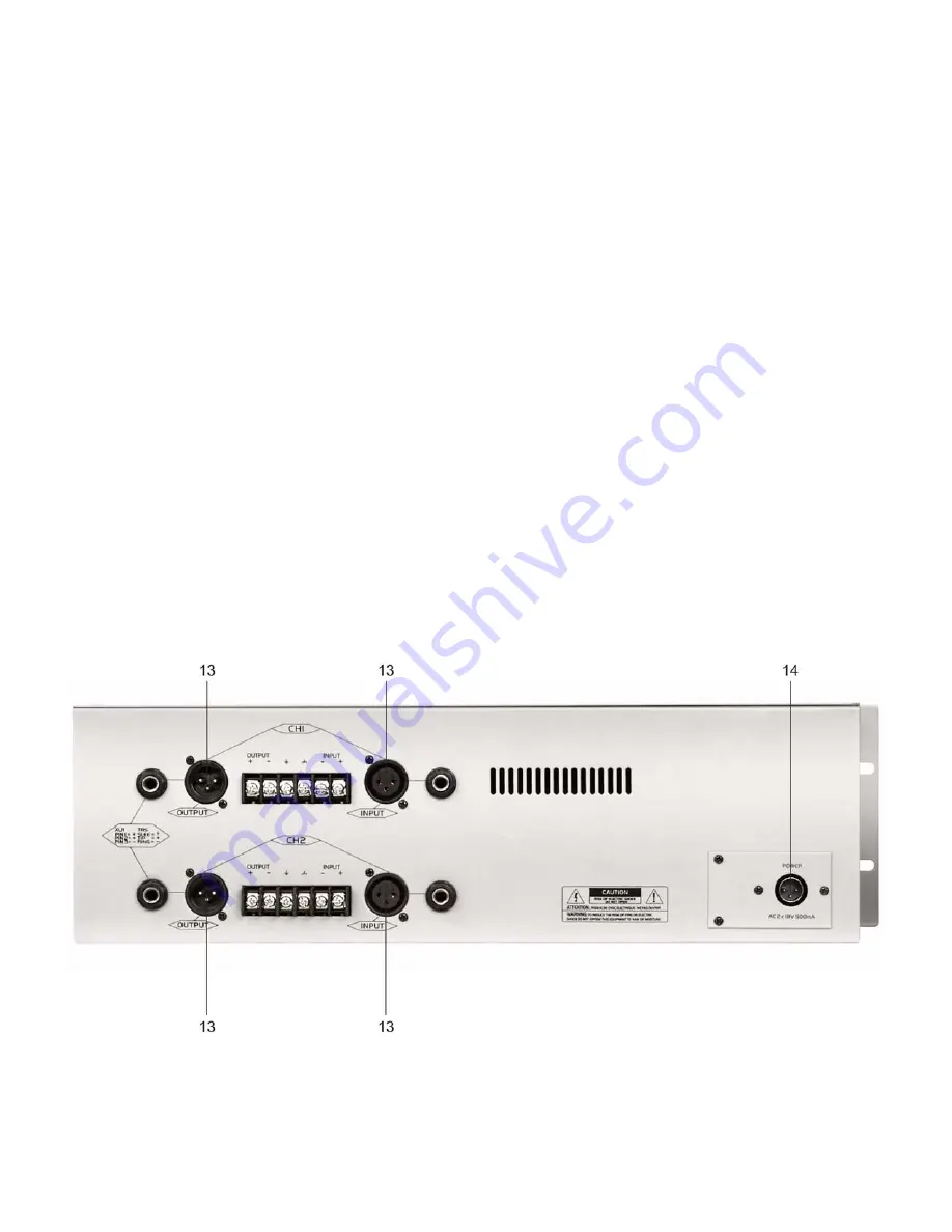
EQ-3231F DESCRIPTION REAR PANEL:
13. Input / Output Connector -
1
/
4
” Stereo Jack (Balanced)
The
1
/
4
” stereo jack connector is balanced and wired as Tip=+, Sleeve=Ground, Ring= -.
Summary of Contents for EQ-3231F
Page 1: ...EQ 3231F ORDERCODE D1923...
Page 12: ...2004 DapAudio...


