background image

5

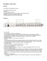
8. Low Mute Button
    Press the button and the low frequency signal has no output and the LED on the left will light up.
9. High Frequency Output Gain
    This knob is to adjust the Low or Mid  frequency output level of the Mid frequency or stereo channel
    signal. The range is fully adjustable from -

 to +12dB.

10. High Mute Button
      Press the button and the High frequency signal has no output and the Led on the left will light up.
11. SUB Frequency Control
      This knob is to adjust the SUB Frequency of the ACX-23S. The range is fully adjustable from
      40 Hz to 300 Hz.
12. SUB Output Gain
      This knob is to adjust the SUB output level. The range is fully adjustable from -

 to +12dB.

      When only one channel has input, the output gain is adjustable from -

 to +6dB.

      When two channels have input, the output gain is adjustable from -

 to +12dB.

      The special SUB channel of the ACX-23S provides a strong low frequency signal. This is a separate
      channel, which can be used to build one SUB s two channel Mid-High speakers for a low cost
      system, or build one SUB s two Low + two High speakers for a high performance system.

ACX-23S DESCRIPTION REAR PANEL:

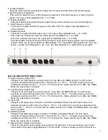
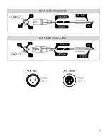
13. High Frequency Output XLR
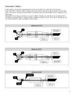
      This jack is the high frequency output connector, it has BAL and UNBAL Mode. The XLR output
      connector is balanced and wired as Pin 1=Ground, Pin 2=+, Pin 3= -. The XLR output connector is
      unbalanced and wired as Pin 1= -, Pin 2=+, Pin 3=Ground. No matter whether it is on BAL and UNBAL
      Mode, the output level is constant.
14. Low Frequency Output XLR
      This jack is the low frequency output connector, it has BAL and UNBAL Mode. The XLR output
      connector is balanced and wired as Pin 1=Ground, Pin 2=+, Pin 3= -. The XLR output connector is
      unbalanced and wired as Pin 1= -, Pin 2=+, Pin 3=Ground. No matter whether it is on BAL and UNBAL
      Mode, the output level is constant.
15. Input XLR
      This jack is the signal input connector, it has BAL and UNBAL Mode. The XLR input connector is
      balanced and wired as Pin 1=Ground, Pin 2=+, Pin 3= -. The XLR input connector is unbalanced and
      wired as Pin 1= -, Pin 2=+, Pin 3=Ground. No matter whether it is on BAL and UNBAL Mode, the output
      level is constant.
16. SUB Output XLR
      This jack is the SUB signal output connector, it has BAL and UNBAL Mode. The XLR output
      connector is balanced and wired as Pin 1=Ground, Pin 2=+, Pin 3= -. The XLR output connector is
      unbalanced and wired as Pin 1= -, Pin 2=+, Pin 3=Ground. No matter whether it is on BAL and UNBAL
      Mode, the output level is constant.
17. Remote Power Supply Input Socket
      This is the remote AC power supply input socket for the ACX-23S. It is a special three cores socket.
      The model for this power supply adapter is “YH-18A-1000”. In order to make your ACX-23S work in a

Summary of Contents for ACX-23S

Page 1: ...ACX 23S ORDERCODE D1937 ...

Page 2: ...P Audio for more excellent audio products We design and manufacture professional audio equipment for the entertainment industry New products are being launched regularly We work hard to keep you our customer satisfied For more information iwant dap audio info You can get some of the best quality best priced products on the market from DAP Audio So next time turn to DAP Audio for more great audio e...

Page 3: ... Audio ACX 23S Product Guide Warning Safety instructions Operating Determinations Description Features Overview Front side Overview Back side Installation Set Up and Operation Connection Cables Maintenance Troubleshooting Product Specifications ...

Page 4: ... unit Never use anything to cover the ground contact Do not insert objects into air vents Do not connect this system to a dimmerpack Do not switch the system on and off in short intervals as this would reduce the system s life Do not open this device Risk hazardous radiation exposure Do not run the output of any amplifier channel back into another channel s input Do not connect parallel or series ...

Page 5: ...mode switch Sometimes when you want to send one signal to more than one amplifier you should use a signal distributor Extreme frequency boosts in connection with a high input signal level may lead to overdriving your equipment Should this occur it is necessary to reduce the input signal level by using the INPUT control To emphasize a frequency range you don t necessarily have to move its respectiv...

Page 6: ...le indicating the signal is sometimes clipped When the LED frequently flashes the signal is clipped often You should reduce the input to the point the LED is not flashing anymore 4 Input Gain Control This control allows you to adjust the input level from to 6dB NOTE Too much adjustment can distort the signal 5 Crossover Frequency Control This knob is to adjust the crossover frequency The range is ...

Page 7: ... Mode The XLR output connector is balanced and wired as Pin 1 Ground Pin 2 Pin 3 The XLR output connector is unbalanced and wired as Pin 1 Pin 2 Pin 3 Ground No matter whether it is on BAL and UNBAL Mode the output level is constant 14 Low Frequency Output XLR This jack is the low frequency output connector it has BAL and UNBAL Mode The XLR output connector is balanced and wired as Pin 1 Ground Pi...

Page 8: ...curved Do not supply power before all components of the system are set up and connected properly 1 Stereo 2 way and SUB output combined Each group frequency is designed with an independent mute switch 2 The 24 dB decuple frequency filter provides a sharper crossover frequency and improve the speaker s analytic ability 3 Make sure the Low frequency output phase adjust function is the same phase as ...

Page 9: ...g knots and twists when coiling them This gives the advantage of increasing their life and reliability which is always to your advantage Periodically check that your cables are in good condition that they are correctly wired and that all their contacts are perfectly efficient a great number of problems faulty contacts ground hum discharges etc are caused entirely by using unsuitable or faulty cabl...

Page 10: ...8 ...

Page 11: ...ubleshooting Dap Audio ACX 23S This troubleshooting guide is meant to help solve simple problems If a problem occurs carry out the steps below in sequence until a solution is found Once the unit operates properly do not carry out following steps 1 If the device does not operate properly unplug the device 2 Check the power from the wall all cables etc 3 If all of the above appears to be O K plug th...

Page 12: ...in 6dB Low output gain 12dB High output gain 12dB SUB frequency range 40 Hz 300 Hz SUB output gain 12dB Indicator Power Clip Low mute High mute Input impedance Balanced 20 KΩ Unbalanced 10 KΩ Output impedance Balanced 300 Ω Unbalanced 150 Ω Input connector XLR 1 G 2 3 Output connector XLR 1 G 2 3 Dimensions 483 x 115 x 44 5 mm LxWxH Weight 2 kg Design and product specifications are subject to chan...

Page 13: ...2004 DapAudio ...

Reviews: