


Generator
143
Copyright © DapTechnology B.V., 2005-2019 - All Rights Reserved., 5/20/2019
Clear
Clear the uploaded Generator definition from the Analyzer.
Slot Definitions
With this command, the slot definition editor can be opened. For a description of how it works, please
refer to the
Frame Settings
With this command, the frame settings dialog can be opened. For a description of how it works, please
refer to the
Windows
From the 'Windows' menu you can open one of the other windows of the Analyzer.
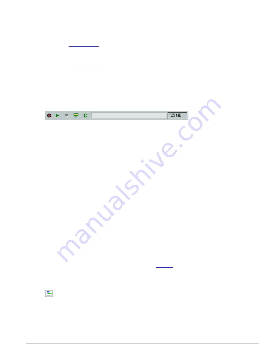
10.1.2.2. Toolbar
The toolbar contains respectively the following items:
Generator active indicator
This red indicator lights when the isochronous Generator is active. The Generator is active when it is
started and has not stopped yet. An active isochronous Generator does not always mean that it is actually
generating packets, because it can be waiting for the next isochronous cycle start to generate the next
packet or it can be in the middle of cycles for which no isochronous packets are defined.
Start isochronous generator
Clicking this button will activate the isochronous Generator. The uploaded isochronous packets will be
generated for the defined cycle, where cycle 0 corresponds to the current isochronous cycle at the
moment the Generator is started. If the isochronous generator data has been changed since the last
upload, the user will first be asked if the changed data must be uploaded again.
Stop isochronous generator
Clicking this button will stop (deactivate) the isochronous Generator.
Upload isochronous generator data to Analyzer
Clicking this button will result in the uploading of the isochronous generator data to the Analyzer. During
the upload, the packets are actually created. This means that some errors may be detected. If packet data
is to be read from a file for instance, the file may not be found. Or the generated packet length may be
larger than specified in the 'Max Data Length' box. In both cases the user will be asked if to abort the
upload or to ignore the error.
Clear isochronous generator memory
Clicking this button will clear the isochronous data, which is uploaded to the Analyzer generator memory.
Before new data can be uploaded, the old must be cleared. When uploading new data the user will be
asked if the old data should be cleared (if there is already some uploaded isochronous generator data),
but you could also clear the memory manually before uploading new data. The generator memory also
needs to be cleared when changing memory sizes, see
for more information about changing the
generator memory size.
10.1.2.3. Slot Definitions
You can add and remove slots and change the properties of slots (like associated channel number and
offset time), by clicking the 'Select slots' button. This button can be found in the upper left corner. When
clicked, a dialog shows up. In this dialog you can change slot properties and add or remove slots. Using
the import button in this dialog, you can read the slot information from a file (comma separated values).
The Analyzer supports a maximum of 61 slots except the FireSpy 400b and 800 which support a
maximum of 31 slots.
Summary of Contents for 1394
Page 1: ...1394 Analyzer Operation Manual Hardware and Software Guide Doc DT PRO134MAN700E ...
Page 11: ...1394AnalyzerOperationManual 11 456 The SCSI2 Connector 457 The SUBD connector ...
Page 187: ...Scriptor 187 Copyright DapTechnology B V 2005 2019 All Rights Reserved 5 20 2019 ...
Page 199: ...Scriptor 199 Copyright DapTechnology B V 2005 2019 All Rights Reserved 5 20 2019 ...
Page 363: ...FormatEditor 363 Copyright DapTechnology B V 2005 2019 All Rights Reserved 5 20 2019 ...


