10
Description of the cooling system
Description
In the front section of the unit the evaporator (cooling coil) is mounted together with an
expansion valve and the sight glass.
The condenser, the compressor and the rest of the components are housed in the rear
section.
The cooling circuit is completely sealed and filled with refrigerant (R134a).
Description of the cooling process:
From the receiver liquid refrigerant will flow under high pressure through the liquid line
dryer and the sight glass to the thermostatic expansion valve. Here the refrigerant is led
into the evaporator where it evaporates at low pressure and low temperatures. The
evaporated refrigerant is drawn back to the hermetic compressor and compressed.
From the compressor the refrigerant vapour goes to the condenser, where it is cooled
to below dew point and condensed to liquid refrigerant because of the cooling effect
from the condenser airflow. Both evaporator and condenser are heat exchangers with
copper tubes and coated aluminium fins. By the cooling of the evaporator air stream
heat is adapted to the cooling circuit and released in the condenser together with the
electric energy consumption of the compressor.
At ambient temperatures below 18-20 °C, where cooling is not normally required, the
humidity in the airflow will form ice on the evaporator. This will generate a Low pressure
(LP) condition. The compressor will stop until the ice has melted. At high ambient tem-
peratures (above 60 °C) the cooling of the condenser airflow will be too low, and the
high pressure results in cut out of the HP pressure switch.
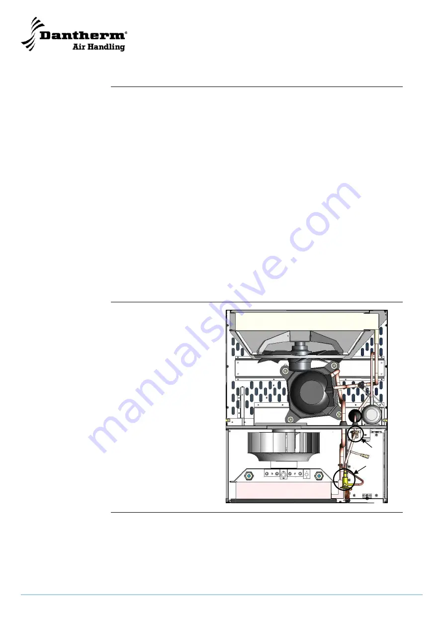
Illustration
This illustrates the cooling
system and internal compo-
nents of the AC-M5 W MKII:
Continued overleaf
c
d
e
f
g
h
i
j


