


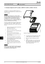


12 Busbar Adjustment Procedure (MCD5-0360C to MCD5-1600C)
The busbars on non-bypassed models MCD5-0360C to
MCD5-1600C can be adjusted for top or bottom input and
output as required.
NOTICE
Many electronic components are sensitive to static
electricity. Voltages so low that they cannot be felt, seen,
or heard can reduce the life, affect performance, or
completely destroy sensitive electronic components.
When performing service, use proper ESD equipment to
prevent possible damage from occurring.
All units are manufactured with input and output busbars
at the bottom of the unit as standard. If necessary, the
input and/or output busbars can be moved to the top of
the unit.
1.
Remove all wiring and links from the soft starter
before dismantling the unit.
2.
Remove the unit cover (4 screws).
3.
Remove the LCP front cover, then gently remove
the LCP (2 screws).
4.
Remove the control card terminal plugs.
5.
Gently fold the main plastic away from the soft
starter (12 screws).
6.
Unplug the LCP loom from CON 1 (see
Notice
).
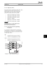
7.
Label each SCR firing loom with the number of
the corresponding terminal on the main control
PCB, then unplug the looms.
8.
Unplug the thermistor, fan, and current
transformer wires from the main control PCB.
9.
Remove the plastic tray from the soft starter (4
screws).
NOTICE
Remove the main plastic slowly to avoid damaging the
LCP wiring loom (wiring harness), which runs between
the main plastic and the backplane PCB.
Illustration 12.1 Removing Front Cover and LCP
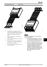
10.
Unscrew and remove the magnetic bypass plates
(models MCD5-0620C to MCD5-1600C only).
11.
Remove the current transformer assembly (3
screws).
12.
Identify which busbars to remove. Remove the
bolts holding these busbars in place, then slide
the busbars out through the bottom of the
starter (4 bolts per busbar).
Busbar Adjustment Procedure...
VLT
®
Soft Starter MCD 500
86
Danfoss A/S © 05/2016 All rights reserved.
MG17K602
12
12


