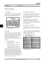
Danfoss VLT OneGearDrive Instruction Manual Download Page 26

8 Motor Datasheet

8.1  Nameplate

The nameplate on the OneGearDrive is corrosion-proof. It
is made of a special plastic, approved for hazardous areas
by the Physikalisch-Technische-Bundesanstalt (PTB).

130BB851.13

INmax 7.2 A

n LT 0..212 rpm

fmax 150 Hz

tamb 40 °C

KTY 84-130

28 kg

P3

IP 69K

155 °C (F)

178uxxxxxxxxxxb011

i 14.13

Type OGDHK214K13140L06XXS31P3A9010H1BXX

Barcode

Made in Germany

M LT  0..230 Nm

3.1 L Optileb GT220

Figure 8.1 Example Nameplate

8.2  Storage

If the OneGearDrive is to be stored, ensure a dry, dust free,
and well-ventilated environment with a low vibration
rating of v

eff

 <0.2 mm/s. If the temperature in the storage

space exceeds the normal range of -4 

°

F to 104 

°

F [-20 

°

C

to 40 

°

C] for an extended period or varies frequently,

employ the measures before start-up specified in

chapter 5.1 Measures before Commissioning

, even after short

storage times.

Damage sustained during storage:

The life of the oils and seals is reduced with
longer storage times.

There is a risk of fracture at low temperatures
(under approximately -4 

°

F [–20 

°

C]).

If the transport eyebolts are replaced, use drop
forged eyebolts as specified in DIN 580.

If the OneGearDrive is being stored for an extended time
before start-up, increased protection against damage by
corrosion or humidity can be achieved by observing the
following information. The actual load depends strongly on
local conditions, therefore the time period stated is only a
guide value. This period does not include any extension of
the warranty. If disassembly is necessary before start-up,
contact Danfoss Service. The instructions contained in this
instruction manual must be observed.

8.2.1 Measures during Storage

Turn the OneGearDrive 180

°

 every 12 months so that the

oil in the gear unit covers the bearings and gearwheels
that were previously positioned on top. Also, turn the
output shaft manually to churn the rolling-contact bearing
grease and distribute it evenly.

The OneGearDrive does not need to be turned if it is
completely filled with oil as the result of a special
agreement. In this case, reduce the oil level before start-up
to the desired value, as defined in 

chapter 6.4.3 Oil Volume

and on the nameplate.

8.2.2 Measures after Storage

Repair any damage to the exterior paint layer or to the
rust protection of the bright metal shafts, including hollow
shafts.

Check that the OneGearDrive contains the correct amount
of oil and that the oil quality has not diminished during
storage. If so, follow the instructions in

chapter 6.4.4 Changing the Oil

.

8.3  Permanent Magnet 3-phase

Synchronous Motor

Rated torque

12.6 Nm

Rated current

7.2 A

Rated speed

3000 RPM

Rated frequency

250 Hz

Motor circuit

Y

Stator resistance (Rs)

0.5 

Ω

Inductivity – D axis (Ld)

5 mH

Inductivity – Q axis (Lq)

5 mH

Motor poles (2p)

10

Moment of inertia

0.0043 Kgm

²

Back EMF constant (ke)

120 V/1000 RPM

Torque constant (kt)

1.75 Nm/A

Table 8.1 Specifications

Motor Datasheet

Instruction Manual

24

Danfoss A/S © 08/2014 All rights reserved.

MG75C422

8

8

Summary of Contents for VLT OneGearDrive

Page 1: ...MAKING MODERN LIVING POSSIBLE Instruction Manual VLT OneGearDrive www danfoss com drives...

Page 2: ......

Page 3: ...7 3 1 Unpacking 7 3 1 1 Items Supplied 7 3 2 Transportation 7 3 2 1 Inspection on Receipt 7 3 2 2 Transport 7 3 3 Protection Rating 7 3 4 Protective Coating 7 3 5 Mounting Arrangement 7 3 5 1 Mountin...

Page 4: ...4 Changing the Oil 22 6 5 Spare Parts 22 7 Decommissioning and Disposal 23 7 1 Dismounting 23 7 2 Product Returns 23 8 Motor Datasheet 24 8 1 Nameplate 24 8 2 Storage 24 8 2 1 Measures during Storage...

Page 5: ...31 8 7 Accessories 32 8 7 1 Accessories for OneGearDrive Standard 32 8 7 2 Accessories for OneGearDrive Hygienic 32 9 Appendix 33 9 1 Glossary 33 9 2 Abbreviations and Conventions 33 9 2 1 Abbreviati...

Page 6: ...before working on or with the OneGearDrive VLT is a registered trademark 1 2 Document Version This document is reviewed and updated regularly All suggestions for improvement are welcome Table 1 1 sho...

Page 7: ...he specified operating conditions and applications Danfoss assumes no liability of any sort for damage attrib utable to improper use 1 5 Approvals 1 6 Disposal Do not dispose of equipment containing e...

Page 8: ...ondition The instruction manual is always available near the OneGearDrive in complete and readable form The OneGearDrive is only fitted installed commissioned and maintained by adequately qualified an...

Page 9: ...The drives are totally enclosed and dust tight as well as hose proof The OneGearDrive Standard is for use in aggressive areas and is supplied in protection rating IP67 as standard The OneGearDrive Hyg...

Page 10: ...2334 82 5 2096 74 8 1901 200 68 1727 59 3 1505 52 5 1334 47 2 1198 42 8 1086 360 55 3 1404 48 2 1223 42 8 1084 38 3 973 34 8 883 Table 3 1 Maximum Force 1 X is the distance from the surface of the ho...

Page 11: ...3 3 The dimensions shown could differ from the customer conditions and must potentially be changed by the customer Mounting instructions Rotate the disc 2 and fit it against the retaining ring 3 Both...

Page 12: ...length used b The dimensions shown could differ from the customer conditions and must potentially be changed by the customer NOTICE Use grease to mount the OneGearDrive onto the shaft For example CAST...

Page 13: ...ith the plastic cap 2 This ensures the hygienic features of a smooth surface 2 Assemble the hollow shaft cover 4 with the three screws 5 onto the OneGearDrive 2a Fasten the screws by hand 2b Using a f...

Page 14: ...g shielded cables is the responsi bility of the system s installers For systems with adjustable frequency drives and rectifiers the manufacturer s electro magnetic compatibility information must also...

Page 15: ...osition of the terminal box or open any screws unless instructed to in this instruction manual Doing so may cause damage to the OneGearDrive and will invalidate the warranty Screw on terminal boxes ar...

Page 16: ...witching duty take the starting current into account Protect the drive unit against overload and in dangerous situations against unintended starts Lock the terminal box again to protect against contac...

Page 17: ...TY 84 130 T1 White 0 75 mm2 AWG 20 1 5 mm2 AWG 16 T2 Brown Table 4 1 Cage Clamp Connections 1 When connected to VLT AutomationDrive FC 302 and VLT Decentral Drive FCD 302 use analog input terminal 54...

Page 18: ...AutomationDrive FC 3021 VLT Decentral Drive FCD 3021 T2 KTY sensor 1 Analog input 54 Table 4 4 Connections T1 and T2 1 Only if connected 4 6 Overload Protection Take note of the relevant circuit diagr...

Page 19: ...commen dations see chapter 6 4 3 Oil Volume Shaft seals Lubricate the hollow shaft seal with grease if the storage period exceeds two years When changing the oil the function of the shaft seals betwee...

Page 20: ...rgely maintenance free The maintenance tasks listed in Table 6 1 may be performed by the customer No other tasks are required Component Maintenance task Maintenance interval Instruction OneGearDrive C...

Page 21: ...he fastening screws 3 6 Close the brake cover and tighten the covering nuts 11 NOTICE After the rotor has been exchanged the complete braking torque will only be effective after the brake linings at t...

Page 22: ...ny 6 4 Oil 6 4 1 Oil Changes The OneGearDrive is supplied with oil ready for operation Table 6 3 shows the oil change intervals based on normal operating conditions and an oil temperature of approxi m...

Page 23: ...fe is only ensured by the use of oil listed in Table 6 4 or an equivalent If the OneGearDrive is stored for a long period before installation refer to chapter 8 2 Storage Only the following wear prote...

Page 24: ...1 Once the OneGearDrive and the oil have cooled down remove the OneGearDrive from your system 2 Bring the OneGearDrive into a vertical position and remove oil screws 1 and 2 3 Turn the OneGearDrive in...

Page 25: ...h the OneGearDrive until it has cooled down Do not carry out an oil change until the oil has cooled sufficiently 7 1 Dismounting 1 Disconnect the supply to the adjustable frequency drive and wait for...

Page 26: ...the time period stated is only a guide value This period does not include any extension of the warranty If disassembly is necessary before start up contact Danfoss Service The instructions contained...

Page 27: ...ironmental Conditions 8 5 Dimensions 8 5 1 OneGearDrive Standard 130BB939 14 8 04 7 85 2 91 4 53 2 91 5 79 3 09 7 24 5 98 5 20 11 30 4 80 7 28 7 20 3 54 0 14 3 74 j6 1 82 M10x20 deep Figure 8 2 OneGea...

Page 28: ...7 JS9 0 007 1 57 130BB943 12 Figure 8 5 Steel Stainless Steel 40 8 5 2 OneGearDrive Standard with Torque Arm in Front Position optional 130BB947 12 8 04 2 91 4 94 0 75 7 28 2 91 5 79 3 09 1 82 11 30 4...

Page 29: ...OneGearDrive Hygienic 130BB935 12 1 31 1 48 3 64 1 48 2 89 2 89 7 28 0 31 JS9 0 007 0 05H13 0 05H13 H7 1 18 Figure 8 8 Stainless Steel 30 130BB936 12 1 51 1 48 3 64 1 48 2 89 2 89 7 28 0 06H13 0 39 J...

Page 30: ...OneGearDrive If the plug is rotated the cables could be damaged causing a short circuit Contact Danfoss Service if the plug is not fastened tightly 8 5 4 OneGearDrive Hygienic with Torque Arm in Front...

Page 31: ...t DIN 985 M10 5 Disc 73x3 Stainless steel 6 Customer frame 7 Barrel POM C white 8 Bushing Stainless steel 9 Screw Stainless steel Figure 8 14 Mounting Set NOTICE The set also contains 3xDIN 933 M10x25...

Page 32: ...id any injury to persons or damage to objects caused by operation without a brake WARNING Danger of fatal injury if the hoist falls Severe or fatal injuries Do not use the brake in vertical lifting an...

Page 33: ...al 04 Terminal 123 MBR Table 8 4 Mechanical Brake Option Connections NOTICE Connect terminal 05 on the VLT AutomationDrive FC 302 to the 400 V AC supply The connection and use of the mechanical brake...

Page 34: ...rd 8 7 2 Accessories for OneGearDrive Hygienic OneGearDrive Hygienic Ordering number Motor connector without cable 178H1613 Motor connector with 5 m cable 178H1630 Motor connector with 10 m cable 178H...

Page 35: ...er S1 duty conditions Motor shaft Rotating shaft on the A side of the motor typically without a key groove Mounting set Additional components to fix the torque arm to the conveyor frame and included i...

Page 36: ...other information and description of figures Italicized text indicates Cross reference Link Footnote Parameter name parameter group name or parameter option All dimension drawings are in inches Append...

Page 37: ...Standard with torque arm in front position 26 Disclaimer 4 Dismounting 23 Disposal instructions 5 Due diligence 6 F Faults 20 Frequency rated 24 G Glossary 33 H High voltage 6 I Improper use of the p...

Page 38: ...e 4 Mounting 8 Qualified personnel 6 Symbols 6 Service 5 Shaft seals 17 Spare parts 22 Speed rated 24 Springs brake 19 Start up Measures before commissioning 17 Stator 24 Storage Conditions 24 Measure...

Page 39: ...Index Instruction Manual MG75C422 Danfoss A S 08 2014 All rights reserved 37...

Page 40: ...that alterations to products already on order shall not require material changes in specifications previously agreed upon by Danfoss and the Purchaser All trademarks in this material are property of t...

Reviews: