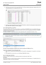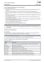
1.
-
-
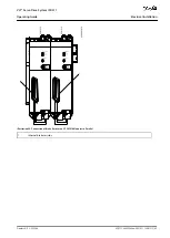
5.9.5 Connecting the Expansion Module EXM 510
12
53
15
8
1
2
3
4
5
6
7
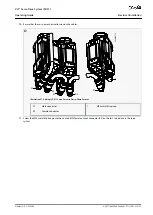
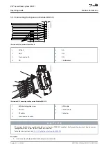
e30bh661.10
Illustration 36: Expansion Module Cable
1
24/48 V
2
GND
3
Functional earth
4
DC–
5
DC–
6
DC+
7
DC+
8
Shielded area
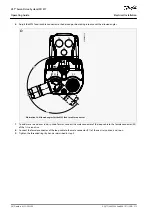
e30bh392.11
1
2
3
4
5
6
7
Illustration 37: Connecting the Expansion Module EXM 510
1
EMC shielding plate screw
2
PE screw
3
DC cables
4
Functional earth cable
5
GND cable
6
24/48 V cable
7
Cable ties
N O T I C E
If 2 separate backlinks are used (connected via 1 or 2 pairs of EXM 510 modules), the 2 grounding bars must be also connec-
ted together with a 16 mm
2
(6 AWG) cable cross-section.
11.6.13.1 Cable Cross-Sections for EXM 510
.
Procedure
Insert wires [3], [4], [5], and [6] into the expansion connector.
AQ377148425069en-000101
/ 130R1213 | 63
Danfoss A/S © 2023.08
Electrical Installation
VLT® Servo Drive System ISD 511
Operating Guide

