


All control terminals and relay terminals 01-03/04-06
comply with PELV (Protective Extra Low Voltage), with the
exception of grounded Delta leg above 400 V.
Galvanic (ensured) isolation is obtained by fulfilling
requirements for higher isolation and by providing the
relevant creepage/clearance distances. These requirements
are described in the EN 61800-5-1 standard.
The components that make up the electrical isolation, as
described below, also comply with the requirements for
higher isolation and the relevant test as described in EN
61800-5-1.
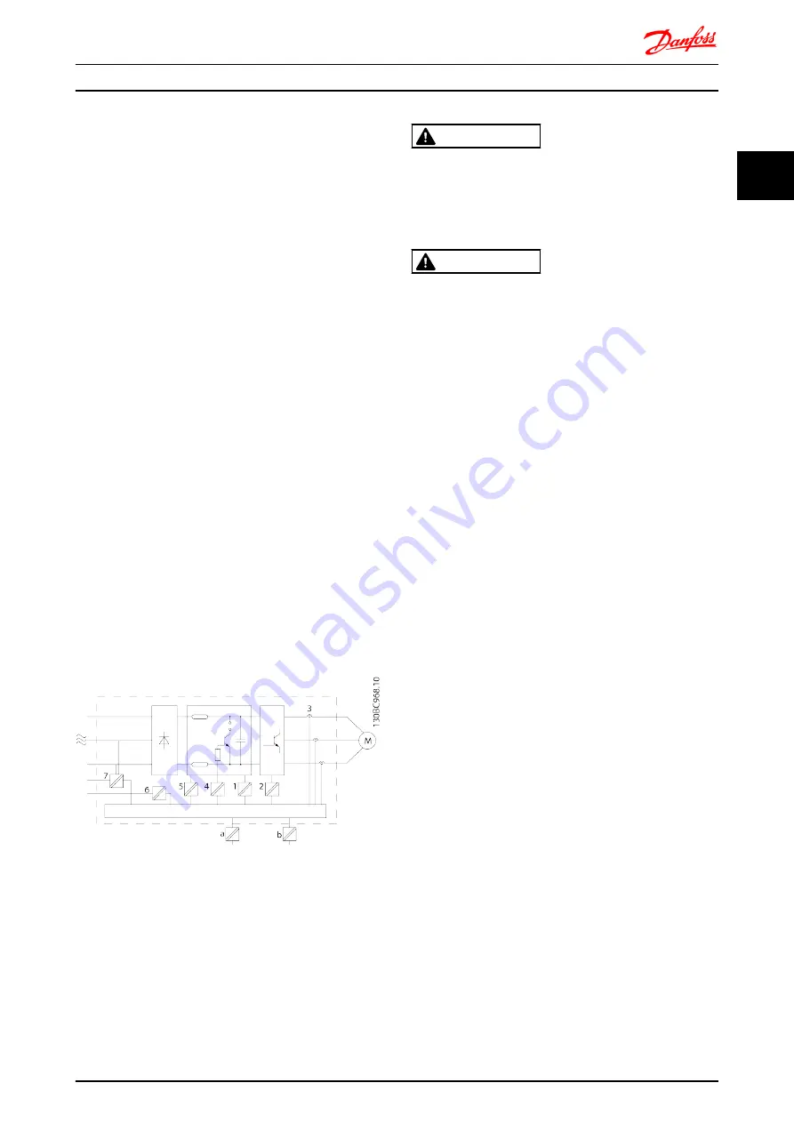
The PELV galvanic isolation can be shown in six locations
(see
):
In order to maintain PELV all connections made to the
control terminals must be PELV, e.g. thermistor must be
reinforced/double insulated.
1.
Power supply (SMPS) incl. signal isolation of U
DC
,
indicating the voltage of intermediate DC Link
circuit.
2.
Gate drive that runs the IGBTs (trigger
transformers/opto-couplers).
3.
Current transducers.
4.
Opto-coupler, brake module.
5.
Internal inrush, RFI, and temperature
measurement circuits.
6.
Custom relays.
7.
Mechanical brake.
Illustration 2.24 Galvanic Isolation
The functional galvanic isolation (a and b on drawing) is
for the 24 V back-up option and for the RS-485 standard
bus interface.
WARNING
Installation at high altitude:
380-500 V: At altitudes above 2 km, contact Danfoss
regarding PELV.
380-500 V: At altitudes above 3 km, contact Danfoss
regarding PELV.
WARNING
Touching the electrical parts could be fatal - even after the
equipment has been disconnected from mains.
Also make sure that other voltage inputs have been
disconnected, such as load sharing (linkage of DC
intermediate circuit), as well as the motor connection for
kinetic back-up.
Before touching any electrical parts, wait at least the
amount of time indicated in
Introduction, in FCD 302,
Operating Instructions, MG04F
.
Shorter time is allowed only if indicated on the nameplate
for the specific unit.
2.6 Mechanical Brake
2.6.1 Hoist Mechanical Brake
For an example of advanced mechanical brake control for
hoisting applications, see
.
2.6.2 Brake Resistor Cabling
EMC (twisted cables/shielding)
To reduce the electrical noise from the wires between the
brake resistor and the frequency converter, the wires must
be twisted.
For enhanced EMC performance, use a metal screen.
2.7 Brake Functions
Braking function is applied for braking the load on the
motor shaft, either as dynamic braking or static braking.
2.7.1 Mechanical Holding Brake
A mechanical holding brake mounted directly on the
motor shaft normally performs static braking. In some
applications the static holding torque is working as static
holding of the motor shaft (usually synchronous
permanent motors). A holding brake is either controlled by
a PLC or directly by a digital output from the frequency
converter (relay or solid state).
Product Overview
VLT
®
Decentral Drive FCD 302
MG04H102 - VLT
®
is a registered Danfoss trademark
25
2
2