


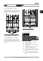


A door fan or fans are required on the enclosure to
remove the heat not contained in the backchannel of the
adjustable frequency drives and any additional losses
generated by other components inside the enclosure. The
total required air flow must be calculated so that the
appropriate fans can be selected.
Airflow
The necessary airflow over the heatsink must be ensured.
The flow rate is shown in
.
The fan runs for the following reasons:
•
AMA
•
DC Hold
•
Pre-Mag
•
DC Brake
•
60% of nominal current is exceeded
•
Specific heatsink temperature exceeded (power
size dependent)
•
Specific Power Card ambient temperature
exceeded (power size-dependent)
•
Specific Control Card ambient temperature
exceeded
Frame
Door fan/top fan
Heatsink fan
D1h/D3h
102 m
3
/hr (60 CFM)
420 m
3
/hr (250 CFM)
D2h/D4h
204 m
3
/hr (120 CFM)
840 m
3
/hr (500 CFM)
Table 2.2 Airflow
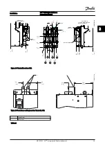
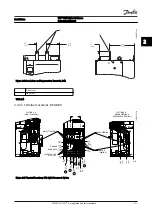
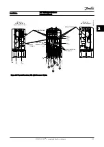
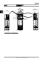
2.3.2 Lifting
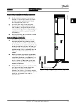
Always lift the adjustable frequency drive using the
dedicated lifting eyes. Use a bar to avoid bending the
lifting holes.
CAUTION
The angle from the top of the adjustable frequency drive
to the lifting cables should be 60
°
or greater.
130BC525.10
Figure 2.1 Recommended Lifting Method
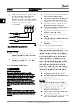
2.3.3 Wall Mounting - IP21 (NEMA 1) and
IP54 (NEMA 12) Units
Consider the following before selecting the final instal-
lation site:
•
Clearance space for cooling
•
Clearance for opening the door
•
Cable entry clearance from the bottom
Installation
VLT
®
HVAC Drive D-Frame
Instruction Manual
2-2
MG16D222 - VLT
®
is a registered Danfoss trademark
2
2


