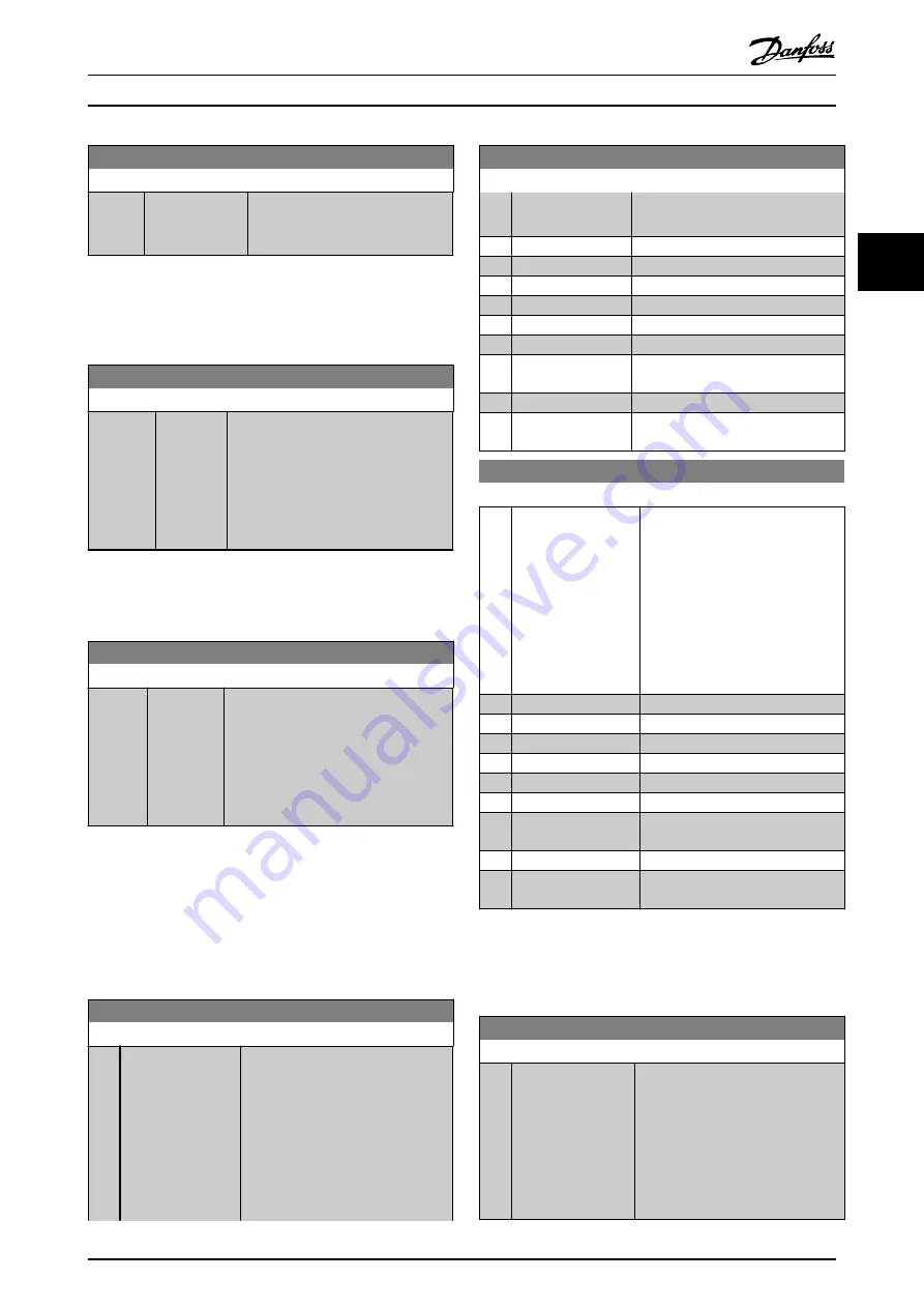
4-17 Torque Limit Generator Mode
Range:
Function:
100.0 %
*
[ 0.0 - 1000.0 %] This function limits the torque on
the shaft to protect the mechanical
installation.
NOTE
The torque limit reacts on the actual, non-filtrated torque,
including torque spikes. This is not the torque that is seen
from the or the as that is filtered.
4-18 Current Limit
Range:
Function:
Size
related
*
[ 1.0 -
1000.0 %]
This is a true current limit function that
continues in the oversynchronous
range, however due to field weakening
the motor torque at current limit will
drop accordingly when the voltage
increase stops above the synchronised
speed of the motor.
NOTE
If [20] is selected in
current limit must be set to 150%.
4-19 Max Output Frequency
Range:
Function:
132.0
Hz
*
[1.0 -
1000.0 Hz]
Provides a final limit on the output
frequency for improved safety in
applications where you want to avoid
accidental over-speeding. This limit is
final in all configurations (independent
of the setting in
NOTE
This parameter cannot be adjusted while the motor is
running.
NOTE
Max. output frequency cannot exceed 10% of the inverter
switching frequency (
).
4-20 Torque Limit Factor Source
Option:
Function:
Select an analog input for scaling the
settings in
and
from 0% to 100% (or inverse).
The signal levels corresponding to
0% and 100% are defined in the
analog input scaling, e.g. parameter
group 6-1*. This parameter is only
active when
4-20 Torque Limit Factor Source
Option:
Function:
is in
Speed Open Loop
or
Speed Closed
Loop
.
[0]
*
No function
[2]
Analog in 53
[4]
Analog in 53 inv
[6]
Analog in 54
[8]
Analog in 54 inv
[10] Analog in X30-11
[12] Analog in X30-11
inv
[14] Analog in X30-12
[16] Analog in X30-12
inv
4-21 Speed Limit Factor SourceOption
Option:
Function:
Select an analog input for scaling
the settings in
from 0% to 100% (or vice
versa). The signal levels
corresponding to 0% and 100% are
defined in the analog input scaling,
e.g. parameter group 6-1*. This
parameter is only active when
is in
Torque
Mode
.
[0]
*
No function
[2]
Analog input 53
[4]
Analog input 53 inv
[6]
Analog input 54
[8]
Analog input 54 inv
[10] Analog input X30-11
[12] Analog input X30-11
inv
[14] Analog input X30-12
[16] Analog input X30-12
inv
3.6.2 4-3* Motor Feedback Monitoring
The parameter group includes monitoring and handling of
motor feedback devices as encoders, resolvers etc.
4-30 Motor Feedback Loss Function
Option:
Function:
Select which reaction the should
take if a feedback fault is detected.
The selected action is to take place
when the feedback signal differs
from the output speed by the value
set in
for longer than the value set
in
4-32 Motor Feedback Loss Timeout
Parameter Descriptions
VLT
®
AutomationDrive Programmming Guide
MG33ME02 - VLT
®
is a registered Danfoss trademark
67
3
3


