


© Danfoss | DCS (ms) | 2020.11
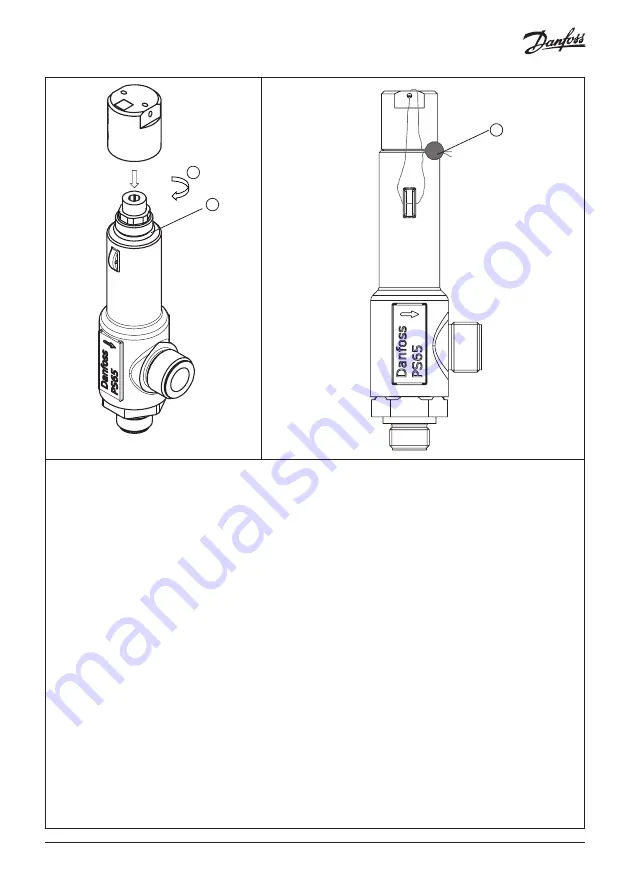
90 Nm
66.4 ft lb
Fig. 13. Fasten cap
Fig. 14. Reseal SFA
In addition to the instructions below, all inspection, repair and recalibration must comply with all local laws and
requirements.
Inspection
When due for service or after the safety valve has been activated it is recommended to disassemble and clean the valve
seat for dirt and particles. The valve must not be disassembled while installed/in operation. Servicing of the valve is only
allowed when valve is dismantled. Apply torque to the inlet body hexagon only and not on the valve body when disman-
tling the safety valve from the changeover valve or pipe fitting. All external sealings must be changed during service using
the 148F3068 SFA 10(H) / DSV 10 inspection kit.
Corrosion
Dust, dirt, corrosion or sticky medias on moving and guiding parts may influence the valve function negatively. If any part
(including the spring) inside the valve are corroded, the valve should be fully replaced. Dirt and particles must be fully
removed. In extreme environments it is recommended to use a valve with bellow instead. This will protect the valve from
refrigerant contaminated with dirt and particles.
Springs
Observe! When cleaning or replacing the spring, it is very important that the exact same spring type is being used. The
spring type can be identified by the color of first windings. Even though it may be possible to set the correct pressure with
a wrong spring, the opening and closing characteristics may be compromised and may lead to reduced lift, leading to lack
of valve capacity and increased system pressure, increased blowdown, leading to extraordinary loss of charge
Temperature ageing
The O-ring material ages when exposed to atmosphere and/or long-term high temperatures. Max. temperature is 100 °C
(212 °F) during activation. If this temperature is exceeded the valve may not reseat perfectly leading to loss of refrigerant.
At static temperatures above 60 °C (140 °F) the lifetime of the O-ring will be gradually reduced, and the valve should be
serviced more frequently, using Danfoss SFA 10(H) repair kit.
Repairing the SFA 10(H)
The Cone and O-ring can be replaced using one the Danfoss SFA 10(H) repair kits. Observe that the repair kits are covering
different set pressure ranges and that purchased repair kit matches the set pressure of the valve to be repaired.
Recalibration and leak test
To verify the valve function after service or inspection following tests should be done by authorized personnel. Danfoss
cannot be held responsible for correct function / set pressure after recalibration.
2
1
1
AN352739267283en-000101 | 5


