Product specification
Power supply
230 V ac, ±10%, 50/60 Hz
Switching action
1 x SPDT volt free type 1B
Switch rating
3(1)A
Temperature range
5-30°C
Max. temperature
45°C
Dimensions, mm
(W, H, D) 85 x 86 x 42
Design standard
EN 60730-2-9
Control pollution
Degree 2
Rated impulse voltage
2.5Kv
Ball hardness
75°C
Installation Instructions
Product overview
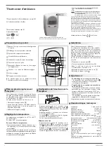
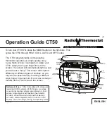
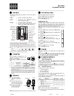
The RET MD is an intelligent room thermostat that, when used in
conjunction with a programmer or timeswitch, provides an energy saving
time delay between programmed switch-on and the actual start of the
heating system. The duration of the delay is dependent upon how
close to set-point the ambient room temperature already is.
Installation
1. The product should only be installed by a qualified electrician or
competent heating installer. The installation must be in accordance
with the current edition of the IEEE wiring regulations.
2. The thermostat must be located at a height of 1.5 metres out of
direct sunlight, away from other heat sources and out of draughts.
3. There must be clearances of at least 30mm right, left and above,
and 100mm below in order to mount the plug-on module.
4. The wallplate must be securely mounted either directly to the wall,
using suitable wood screws, or to a flush mounted 1-gang electrical
accessory box using M3.5 screws.
5. Cable access can either be from behind for concealed cabling or
from below for surface cabling. If surface cable is used, cut out cable
access slot on plug-on module prior to mounting the module.
6. For wiring connections refer to Diagram 1 below. All models are
double insulated and do not require an earth connection. However a
parking terminal is provided on the wallplate, which is clearly marked
with an Earth symbol.
7. Prior to mounting the plug-on module, DIL switches on the rear of
the plug-on module must be set. See Diagram 2 below for available
options.
8. Mount plug-on module to wallplate by locating tabs on top of
wallplate in apertures on rear of module, hinge down and press firmly
to wallplate before tightening securing screws on bottom of wallplate.
Diagram 1. - Wiring
Diagram 2. - DIL Switch Settings
No Heating
! "
#
$
Fault Check List
Delay
Start
Enabled
Chrono
Chrono 3
0°C
Delay
Start
Disabled
On/Off
Chrono 6
0°F
0.0
5.0
10.0
15.0
20.0
25.0
30.0
35.0
40.0
45.0
0.0
1.0
2.0
3.0
4.0
5.0
6.0
7.0
Temperature below thermostat setting, °K
Ti
me
del
a
y
a
fter
ti
me
con
trol
s
w
itch-on,
minu
tes
Delay Start Chart
This product complies with the following EC Directives
:
Electro-Magnetic Compatibility Directive.
(EMC)
(89\336\EEC), (92\31\EEC)
Low Voltage Directive.
(LVD)
(73\23\EEC), (93\68\EEC)
Danfoss Randall Ltd
Ampthill Road, Bedford, MK42 9ER
Tel: 01234 364621
Fax: 01234 219705
Email: [email protected]
Website: www.danfoss-randall.co.uk
Part No 25698 Iss 3 06/04
RET MD
Note: For RET MD live supply is from the Time Control output


