52 | © Danfoss | August 2018
AQ00000211
ENGINEERING TOMORROW
sensors are absent, then the FDA can be disabled, to avoid PVED-CLS from going into safe state (refer chapter
, for
details on FDA). Furthermore, if the system is an OSPE/EHi-E or EHi-H system, the Cut-off valve must also be connected
as a boot-up check is done on the Cut-off Valve presence.
Note: The system requires an MMI installed for changing programs, steering devices and steering modes etc.
For further information regarding sub-system requirements, please see the Danfoss document, PVED-CLS Safety Manual.
For further information regarding protocol requirements, please see the Danfoss document, PVED-CLS Communication
protocol.
8.1
WHEEL ANGLE SENSOR
The PVED-CLS can interface with
either
single/dual channel analogue wheel angle sensor
or
dual channel CAN based
wheel angle sensor, but can also be configured to no wheel angle sensor present.
Wheel angle sensor can be configured by parameters WAS interface (P3244) and Redundant WAS present (P3245).
The wheel angle sensor allows the PVED-CLS to perform closed loop position control on the steered wheels of the
vehicle, auto-guidance steering, anti-drift function as well as soft end stop features.
Important
Recommended WAS specification:
WAS on CAN = 1000 counts full scale from full left to full right. Noise less than 3% full scale
WAS analogue = Minimum 3V bandwidth full left to full right. Noise less than 3% full scale.
8.1.1
No Wheel angle sensor
If no wheel angle present in the system, parameter P3244 i.e.
WAS interface
shall be set to NONE. In this case, PVED-
CLS cannot perform closed loop control of the steered wheels, so auto-guidance or closed loop AUX joystick is not
possible. In addition, anti-drift and soft end-stop is impossible. When wheel angle sensor is disabled, the following
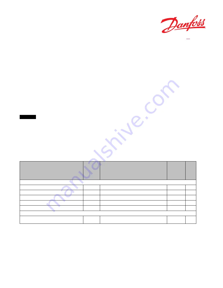
parameters must be set according to Table 22.
Parameter Name
Address
Description of parameter
Expected
Value
Unit
When WAS interface (P3244) == NONE
STW anti-drift - Max flow correction in percentage of full flow
P3569
Max flow correction which can be requested by the EFU algorithm
0
%
AUX anti-drift - Max flow correction in percentages of full flow
P3705
Max flow correction which can be requested by the EFU algorithm
0
%
Valve type
P3081
Valve type on which the PVED-CLS is mounted
Valid Values: 0 (OSPE, EHi); 1 (EHPS)
0
-
GPS present
P3237
GPS Present/Not Present
Valid Values: 0 (NOT PRESENT); 255 (PRESENT)
0
-
GPS2 present
P3238
GPS2 Present/Not Present
Valid Values: 0 (NOT PRESENT); 255 (PRESENT)
0
-
If AUX present (P3239) == TRUE, then
AUX type
P3240
Aux device is mini steering wheel or Joystick
Valid Values: 0 (Open Loop Joystick); 1 (Closed Loop Joystick); 2
(mini steering wheel); 3 (Analogue Joystick);20 (Elobau joystick)
≠1
-
Table 22
If these rules are not followed, PVED-CLS will enter safe state.
8.2
SPEED SENSOR
Many of the PVED-CLS’s safety functions are relying on a safe and trustworthy vehicle speed signal. The PVED-CLS is
performing crosschecks on the vehicle speed signal, therefore it is also required to send (on the CAN bus) two independent
vehicle speed signals (e.g. from two sensor sub-systems).
Summary of Contents for PVED-CLS
Page 6: ...6 Danfoss August 2018 AQ00000211 ENGINEERING TOMORROW ...
Page 71: ... Danfoss August 2018 AQ00000211 71 ENGINEERING TOMORROW Figure 29 ...
Page 127: ... Danfoss August 2018 AQ00000211 127 ENGINEERING TOMORROW ...
Page 147: ... Danfoss August 2018 AQ00000211 147 ENGINEERING TOMORROW ...
Page 182: ...182 Danfoss August 2018 AQ00000211 ENGINEERING TOMORROW ...


