


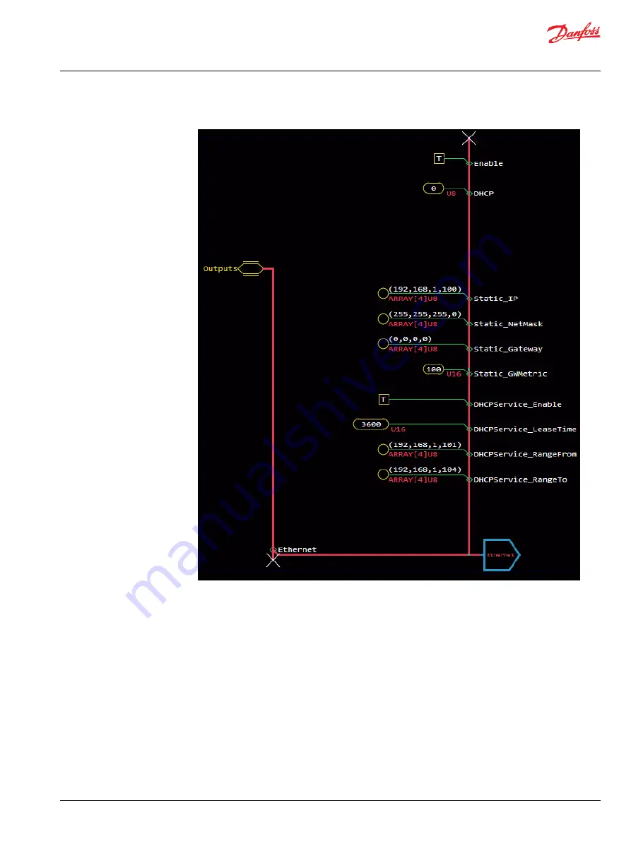
2. Configure the values to resemble the image:
a) Set the DHCP value to 0 to ensure the XM100 takes up the static configuration setting. Any unique
address within the 192,168,1 subnet works, but it should be limited to a range of four numbers for
debugging purposes. The IP address of the XM100 in the example is 192,168,1,100.
b) Set DHCPService_Enable to true. This allows the XM100 controller to act as the DHCP server and
assign IP addresses to other devices in the same local area network (LAN).
c) Set the DHCPService_RangeFrom to an IP address range close to the XM100's. The example here
is 192,168,1,101.
d) Set the DHCPService_RangeTo to an IP address range within four numbers of the XM100's. The
example here is 192,168,1,104. Now the XM100 can assign IP addresses to four devices on the
network smart switch: the switch, two Ouster LiDAR hardware, and the computer.
3. Go back to the Ouster LiDAR compliance block in the application.
a) Enter Ouster_LiDAR_1 > Parameters.
b) Set the IP_Address parameter to an unused IP address within the assigned range. For example,
192,168,1,102.
c) Enter Ouster_LiDAR_2 > Parameters.
d) Set the IP_Address parameter to an unused IP address within the assigned range. For example,
192,168,1,103.
User Manual
Ouster LiDAR
Configure Multiple LiDARs
©
Danfoss | March 2023
AQ404281942428en-000103 | 29


