background image

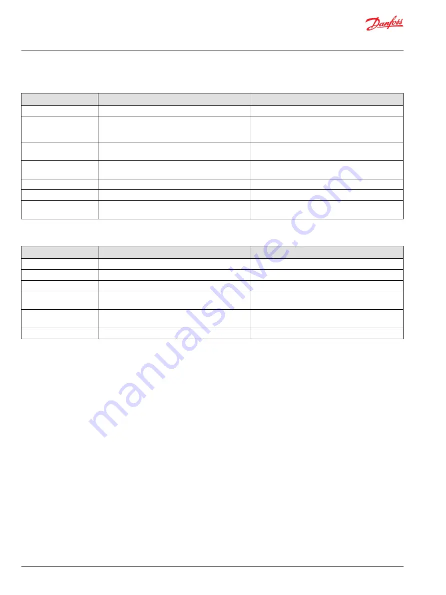
System Noise or Vibration

Item

Description

Action

Reservoir oil level

Low oil level leads to cavitation.

Fill reservoir.

Aeration of the oil/charge
inlet vacuum

Air in the system decreases efficiency of units and controls.
Air in the system is indicated by excessive noise in HST,
foaming in oil, and hot oil.

Find location where air is entering into the system and
repair. Check that inlet line is not restricted and is proper
size.

Cold oil

If oil is cold, it may be too viscous for proper function and
pump cavitates

Allow the oil to warm up to its normal operating
temperature with engine at idle speed.

Charge inlet vacuum

High inlet vacuum causes noise/cavitation.

Check that inlet line is not restricted and is proper size.
Check filter.

Shaft couplings

A loose shaft coupling causes excessive noise.

Replace loose shaft coupling.

Shaft alignment

Misaligned HST and prime mover shafts create noise.

Align shafts.

Charge check/HPRVs

Unusual noise may indicate sticking valves. Possible
contamination.

Clean/replace valves and test the unit.

Sluggish System Response

Item

Description

Action

Oil level in reservoir

Low oil level causes sluggish response.

Fill reservoir.

Charge check/HPRVs

Incorrect pressure settings affects system reaction time.

Replace charge check/HPRVs

Low prime mover speed

Low engine speed reduces system performance

Adjust engine speed.

Air in system

Air in system produces sluggish system response

Fill tank to proper level. Cycle system slowly for several
minutes to remove air from system.

Charge inlet vacuum

Inlet vacuum is too high resulting in reduced system
pressure.

Measure charge inlet vacuum. Inspect line for proper sizing.
Replace filter. Confirm proper bypass operation.

Control linkage

Linkage operating improperly

Repair or replace control linkage

Service Manual

LDU20/24 Closed Circuit Axial Piston Transmission

Troubleshooting


20 | 

©

 Danfoss | June 2021

AX152886481311en-000304

Summary of Contents for LDU24

Page 1: ...Service Manual LDU20 24 Closed Circuit Axial Piston Transmission www danfoss com...

Page 2: ...document number from AX00000049 and 11071687 to AX152886481311 0304 July 2017 Updated to Engineering Tomorrow 0202 March 2014 Danfoss layout BA January 2011 First edition AA Service Manual LDU20 24 C...

Page 3: ...Displacement Control 11 Control Handle Requirements 11 Operating Parameters Overview 12 Input Speed 12 System Pressure 12 Input Power 12 Charge Pressure 13 Case Pressure 13 Viscosity 13 Temperature 1...

Page 4: ...e check HPRV operation 21 Minor Repair Shaft Seals 22 Removal 22 Inspection 22 Assembly 22 Charge Check HPRV 23 Removal 23 Inspection 23 Reassembly 23 Bypass Valve 24 Removal 24 Inspection 24 Reassemb...

Page 5: ...cedures Remove the unit Prior to performing major repairs remove the unit from the vehicle machine Chock the wheels on the vehicle or lock the mechanism to inhibit movement Be aware that hydraulic flu...

Page 6: ...where a source of ignition may be present Fluid under pressure W Warning Escaping hydraulic fluid under pressure can have sufficient force to penetrate your skin causing serious injury and or infecti...

Page 7: ...ent required Pull out with tool press fit Flatness specification Parallelism specification Cover splines with installation cylinder Mark orientation for reinstallation The symbols above appear in the...

Page 8: ...ne housing with Z shaft configuration Available external charge Bypass valve for the pulling of the vehicle Same shaft center distance as BDU21 85mm Between pump and motor shaft Same drive line design...

Page 9: ...High Pressure Relief Valve P400005 C Caution HPRV s are factory set at a low flow condition Any application or operating condition which leads to elevated HPRV flow will cause a pressure rise with flo...

Page 10: ...winched onto a trailer without operating the prime mover C Caution Excessive speed or extended movement will damage the transmission Avoid excessive speeds and extended load vehicle movement Do not mo...

Page 11: ...irectly to the swashplate trunnion Control lever movement changes the speed and rotating direction of the motor by increasing or decreasing the swashplate angle The control input shaft is configurable...

Page 12: ...mission sufficient to stop and hold the vehicle or machine in the event of hydrostatic drive power loss System Pressure System pressure is the differential pressure between system ports A and B It is...

Page 13: ...sity Maintain fluid viscosity within the recommended range for maximum efficiency and bearing life Minimum viscosity should only occur during brief occasions of maximum ambient temperature and severe...

Page 14: ...4 2 Mass moment of inertia of rotating components Pump side kg m2 slug ft2 0 000936 0 000693 Motor side 0 000928 0 000683 Weight dry kg lb 14 1 31 1 Oil volume Case only liter US gal 1 1 0 28 With pas...

Page 15: ...180 Maximum 104 220 Filtration recommended minimum Cleanliness per ISO 4406 22 18 13 Efficiency charge pressure filtration b ratio b 15 20 75 b 10 10 Efficiency suction and return line filtration b 15...

Page 16: ...s of operation Fluid and Filter Change Interval Reservoir Type Max Oil Change Interval Sealed 2000 Hours Breather 500 Hours C Caution High temperatures and pressures accelerate fluid aging This may re...

Page 17: ...ar psi L1 L2 3 4 16 UNF 5 16 internal hex Case Drain 10 100 MA1 MA2 MB1 MB2 3 4 16 UNF 7 8 hex wrench System Pressure 500 5000 M3 9 16 18 UNF 1 4 internal hex Charge Pressure 50 1000 Port Locations M3...

Page 18: ...ure may damage hydraulic components Check carefully for inlet line leaks Do not run at maximum pressure until system is free of air and fluid has been thoroughly filtered 8 Use a common method to disa...

Page 19: ...at in system Measure system pressure If pressure is too high reduce loads Transmission Operates Normally in One Direction Only Item Description Action Control linkage Control linkage is operating impr...

Page 20: ...igned HST and prime mover shafts create noise Align shafts Charge check HPRVs Unusual noise may indicate sticking valves Possible contamination Clean replace valves and test the unit Sluggish System R...

Page 21: ...s of system contamination such as oil discoloration foam in the oil sludge or small metal particles 4 Remove the transmission C Caution Be careful not to damage solenoids and electrical connections wh...

Page 22: ...tion 2 Using a seal installation tool start the seal into the housing bore Hand press the seal the rest of the way into the housing bore Ensure the seal clears the retaining ring groove in the housing...

Page 23: ...damage or foreign material Reassembly 1 Lubricate and install new O rings N130 P130 on valve seat plug N120 P120 2 Verify that the conical springs N100 P100 are properly retained on the check relief v...

Page 24: ...sary Reassembly 1 Lubricate and install new O ring M110 M130 and backup ring M120 onto cartridge 2 Install the bypass valve cartridge using a 17mm hex wrench Torque to 12 N m 9lbf ft Bypass Valve P108...

Page 25: ...57 8 J400 9 16 18 UNF 1 4 internal hex 35 25 8 Y300 3 4 16 UNF 5 16 internal hex 39 2 29 Plugs J400 J200 J250 J300 J350 L1 L2 REVERSE SIDE Y300 Y300 P108482 MB1 M3 MA1 MB2 MA2 REVERSE SIDE REVERSE SID...

Page 26: ...anfoss Power Solutions US Company 2800 East 13th Street Ames IA 50010 USA Phone 1 515 239 6000 Danfoss Power Solutions Trading Shanghai Co Ltd Building 22 No 1000 Jin Hai Rd Jin Qiao Pudong New Distri...

Reviews: