


NOTE
OVC can not be activated when running a PM motor
(when
1-10 Motor Construction
is set to [1] PM non salient
SPM).
Mains Drop-out
During a mains drop-out, the frequency converter keeps
running until the intermediate circuit voltage drops below
the minimum stop level, which is typically 15% below the
frequency converter's lowest rated supply voltage. The
mains voltage before the drop-out and the motor load
determines how long it takes for the inverter to coast.
Static Overload in VVC
plus
mode
When the frequency converter is overloaded (the torque
limit in
4-16 Torque Limit Motor Mode
/
4-17 Torque Limit
Generator Mode
is reached), the controls reduces the
output frequency to reduce the load.
If the overload is excessive, a current may occur that
makes the frequency converter cut out after approx. 5-10
sec.
Operation within the torque limit is limited in time (0-60
sec.) in
14-25 Trip Delay at Torque Limit
.
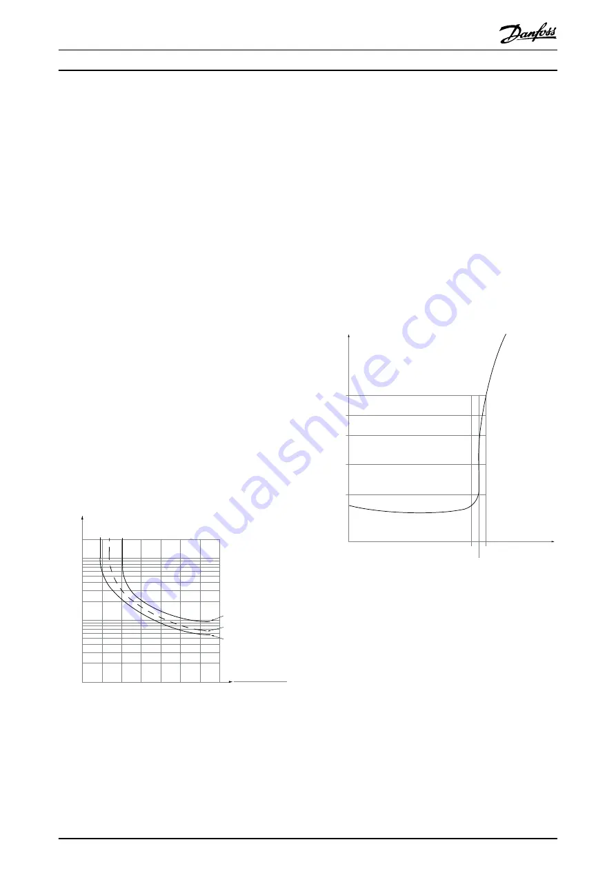
2.13.1 Motor Thermal Protection
This is the way Danfoss is protecting the motor from being
overheated. It is an electronic feature that simulates a
bimetal relay based on internal measurements. The charac-
teristic is shown in
1.2
1.0
1.4
30
10
20
100
60
40
50
1.8
1.6
2.0
2000
500
200
400
300
1000
600
t [s]
175ZA052.12
fOUT = 2 x f M,N
fOUT = 0.2 x f M,N
fOUT = 1 x f M,N(par. 1-23)
I
MN
(par. 1-24)
I
M
Illustration 2.21 The X-axis is showing the ratio between I
motor
and I
motor
nominal. The Y-axis is showing the time in seconds
before the ETR cuts off and trips the frequency converter. The
curves are showing the characteristic nominal speed at twice the
nominal speed and at 0,2x the nominal speed.
It is clear that at lower speed the ETR cuts of at lower heat
due to less cooling of the motor. In that way the motor
are protected from being over heated even at low speed.
The ETR feature is calculating the motor temperature
based on actual current and speed. The calculated
temperature is visible as a read out parameter in
16-18 Motor Thermal
in the frequency converter.
The thermistor cut-out value is > 3k
Ω
.
Integrate a thermistor (PTC sensor) in the motor for
winding protection.
Motor protection can be implemented using a range of
techniques: PTC sensor in motor windings; mechanical
thermal switch (Klixon type); or Electronic Thermal Relay
(ETR).
1330
550
250
-20°C
175HA183.10
4000
3000
R
(Ω)
nominel
nominel -5°C
nominel +5°C
[°C]
VLT
®
HVAC Drive
Quick Reference
Guide