Instructions for installation and use
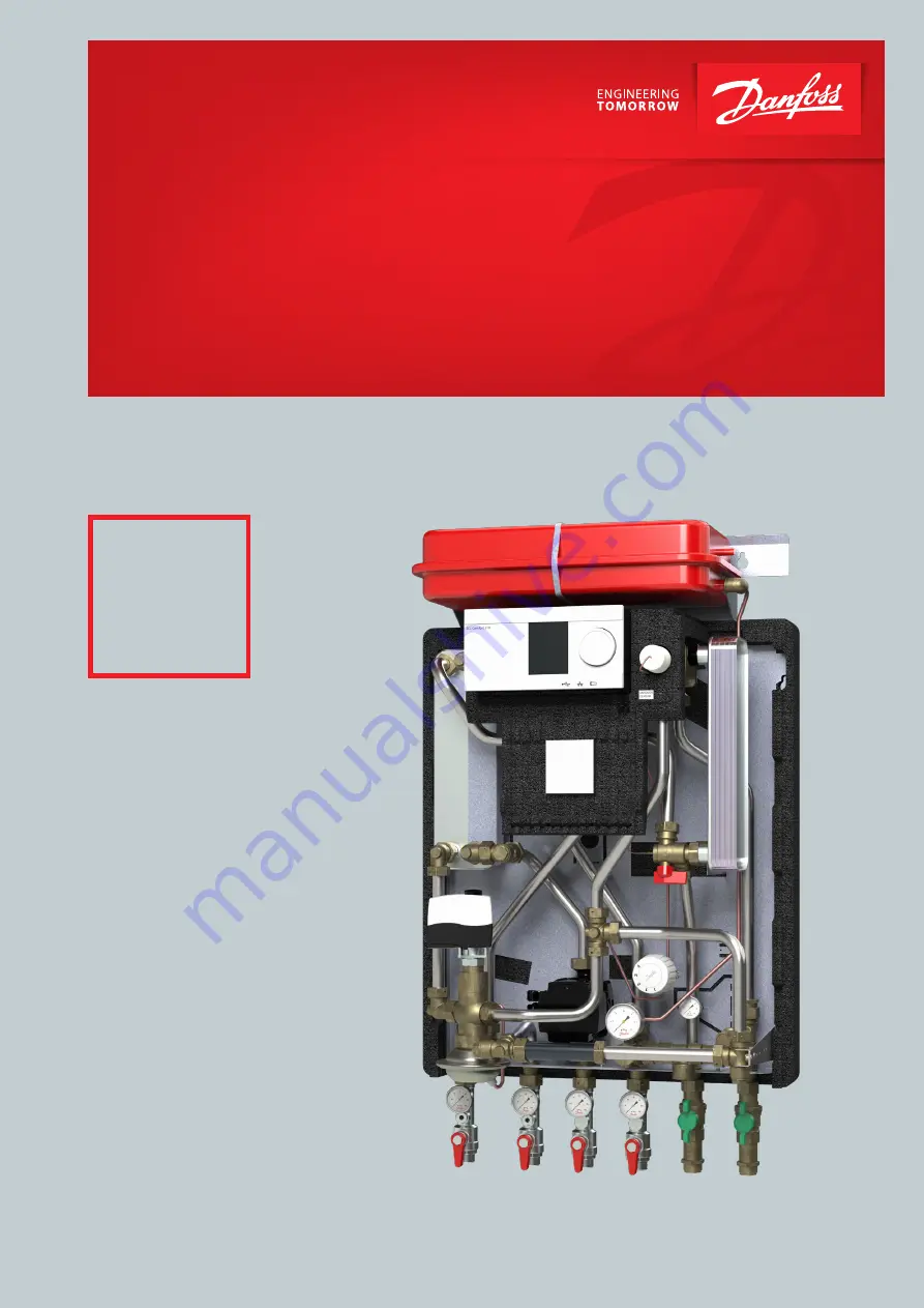
VXe
Fully insulated
for very low
heat losses.
Indirect district heating substation for heating and domestic hot water.
Indirect, fully insulated district
heating subtation
Akva Lux II VXe
www.danfoss.com
Page 1: ...stallation and use VXe Fully insulated for very low heat losses Indirect district heating substation for heating and domestic hot water Indirect fully insulated district heating subtation Akva Lux II...
Page 2: ...r and safety valves 10 7 0 Filling the system with water 11 8 0 Recirculation 12 9 0 Electrical connections 13 10 0 Adjustmend and commissioning 14 11 0 Heating circuit Danfoss ECL 310 automatics 15 1...
Page 3: ...must be stored in a dry heated i e frost free room Relative humidity max 80 and storage temperature 5 70 C Theunitsmustnotbestackedhigherthanthelimitatthefactory max 8layers Unitssuppliedincardboardpa...
Page 4: ...aters districtheatingsta tionsandplumbinginstallations Equipotentialbondingshouldbeinac cordancewiththeprovisions60364 4 41 2007andIEC60364 5 54 2011 Binding point is marked with a grounding symbol on...
Page 5: ...ansion bolts or similar 2 Tighten all pipe connections as they may have loosened during transport and handling 3 Mount the district heating meter see page 11 4 On systems that feature a safety valve e...
Page 6: ...g of heat meter See page 10 Safety valves See page 10 Re circulation See page 12 Electrical connection See page 13 Outdoor sensor Connect to terminal block U Commissioning See page 17 22 Reading of me...
Page 7: ...ET 120 mm for DVGW Circulation pump HE Safety valve HE 3 bar Safety valve DHW 10 bar Thermometer Manometer connection Manometer Expansion vessel 12 L Sensor pocket for heat meter Plugs with O Ring Fit...
Page 8: ...l valve ET ET 120 mm for thermometer manometer Ball valve IT ET 120 mm for thermometer Ball valve ET ET 120 mm for DVGW Circulation pump HE Safety valve HE 3 bar Safety valve DHW 10 bar Thermometer Ma...
Page 9: ...14 Manometer connection 15 Manometer 16 Expansion vessel 12 L 65 100 80 80 80 80 65 1 2 3 4 5 6 550 932 315 55 1 Fjv frem 2 Fjv retur 3 Varme retur 4 Varme frem 5 V V 6 K V Danfoss Standard A3 1 6 Mat...
Page 10: ...ions and shocks during transport and handling may have caused leaks Once the system has been filled with water tighten all the pipe connections once more before performing pres sure test for leaks Aft...
Page 11: ...ng pressure test for leaks Before filling the system with water and starting up check if pipes are connected according to the circuit diagram expansion vessel is connected heat meter is mounted shut o...
Page 12: ...r use a 6 mm Allen key Do not re use the plugs Fig 4 Remove demunt capillary tube onT piece Fig 5 Seal offT piece with a 4 mm plug 5 Fig 6 Fit screw circulation hose end steel hose onto the controller...
Page 13: ...ons The outdoor sensor is always to be mounted on the coldest side of the property where it is less likely o exposed to direct sunshine normally the north side of the property The sensor must not be e...
Page 14: ...according to the instructions on page 11 If the pressure drops below 1 bar water must be added to the sys tem The operating pressure should never exceed 1 5 bar The safety valve opens at 2 5 bar The...
Page 15: ...bed in the instructions on page 15 proceed as follows 1 Connect the controller and switch it on 2 Choose MENU in any circuit Confirm and turn the dial and choose Common controller settings in the circ...
Page 16: ...th electrical actuators AMV and ECL electronic controllers the flow and temperature can be controlled to achieve highest energy savings The controller is equipped with excess pres sure safety valve wh...
Page 17: ...d with a safety thermostat Jumo AT for protection against overheating From factory the Jumo AT safety thermostat is pre wired to the Danfoss ECL controller with a 2 m cable enabling the thermostat hou...
Page 18: ...y to Proportional pressure AUTOadapt The user interface shows performance view during operation operation status alarm status settings view after pressing the button During operation the display shows...
Page 19: ...rm status In case the 1st LED is red the pump has detected one or more alarms See fig 5 Alarm status When there is no active alarm anymore the user interface switches back to operation mode shortly an...
Page 20: ...ve to wait a long time i e more than20sec forhotwater itmaybenecessarytosetthethermostat at a higher value If you want to avoid waiting time altogether you will need to set up domestic hot water recir...
Page 21: ...because aerated water is used on the secondary side If it becomes necessary to clean the exchanger with acid this canbedoneasshownonthedrawingtotheright Brazedplateheat exchangers can withstand rinsi...
Page 22: ...uestionn Clean all dirt filters strainers in the substation Replace any filters that are not intact Check that any electrical cables are in serviceable condition and that it is possible to disconnect...
Page 23: ...the valve housing Automatic components controller incorrectly adjusted or defective or possibly power outage The pump is not working The pump is set at too low speed of rotation not all system types A...
Page 24: ...no air in the pump housing No hot water Dirt strainer in the district heating sup ply line clogged Defective DHW controller Defective sensor PTC2 Clean the dirt strainer Check controller settings You...
Page 25: ...Instructions for installation and use Akva Lux II VXe Danfoss Produced by Danfoss Redan A S 2021 02 25 xxxxxxxxxxxxxxx 17 EU DECLARATION OF CONFORMITY...
Page 26: ...h all technical regulations and the applicable legislation in every respect Installation and commissioning must only be performed by trained authorised personnel The substation is checked in the facto...
Page 27: ...Instructions for installation and use Akva Lux II VXe Danfoss Produced by Danfoss Redan A S 2021 02 27 xxxxxxxxxxxxxxx...
Page 28: ...28 Danfoss Produced by Danfoss Redan A S 2021 02 xxxxxxx...