© Danfoss | 2023.04
LGB53541
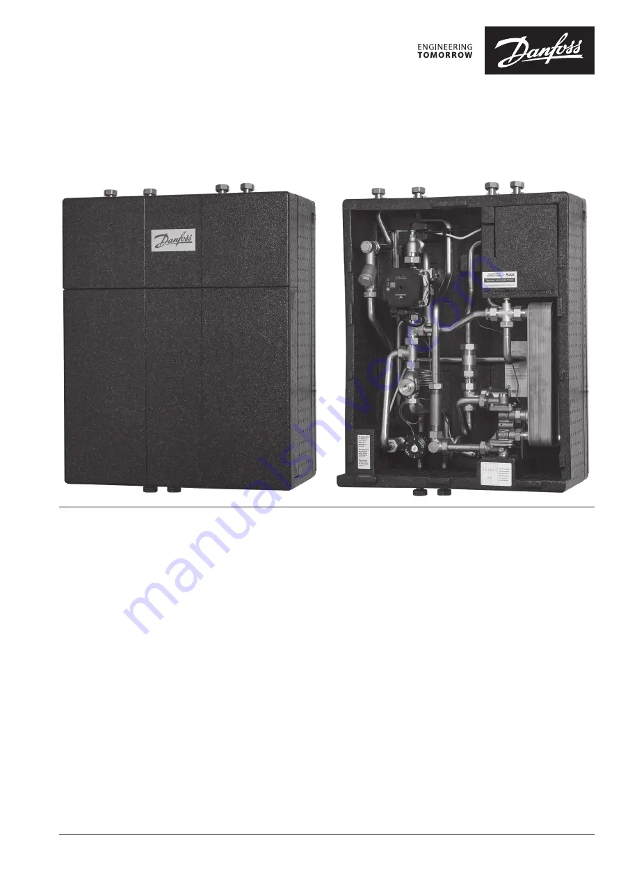
Termix VMTD-IV MIX
- 5 Series DS Fully insulated
Operating Guide
Page 1: ...Danfoss 2023 04 LGB53541 Termix VMTD IV MIX 5 Series DS Fully insulated Operating Guide...
Page 2: ...tion 11 Design 12 Schematic description Termix VMTD IV MIX UFH 13 Electrical connections and wiring 14 Wiring diagram radiator heating 15 Wiring diagram underfloor heating 15 Fitting of energy meter 1...
Page 3: ...d and authorised HVAC technician All electrical connections must be carried out by an authorised electrician Daily operations After correct installation and commissioning under normal circumstances fu...
Page 4: ...ontent in the flow medium should not exceed 150 mg l The risk of corrosion increases significantly if the recommended chloride content is exceeded REACH All products from Gemina Termix A S meet the re...
Page 5: ...eries DS Fully insulated Unit label The unit label is affixed to the back plate Image of a unit label is shown as an example Should the unit label become unreadable damaged or fall off completely then...
Page 6: ...bient temp 0 40 C in continuous use Dimensions for connections DHF DHR HFL HRL DCW DHW G internal thread Weight Net weight 19 22 kg Dimensions Dimensions H 710 mm x W 530 mm x D 270 mm The recommended...
Page 7: ...to vibrations during transport and lifting handling it is important that all union connections are re tightened After filling the system with water and once it is in operation all union connections m...
Page 8: ...the factory Assembly installation and commissioning Unpacking and preparation Remove the packaging from the unit Cling film and cardboard must be disposed of in accordance with locally applicable legi...
Page 9: ...ctions Temporarily remove the inspection hatch Lift the HIU in the following two places 1 With your left hand side around the DHR pipe 2 With your hand side around the DHF pipe that connects to the he...
Page 10: ...U for correct connection of the pipes Please refer to the section Key to symbols Adequate space Please allow adequate space around the HIU for mounting and maintenance purposes Orientation The unit mu...
Page 11: ...Danfoss 2023 04 11 LGB53541 Termix VMTD IV MIX 5 Series DS Fully insulated Dismantling the insulation Disassembly of the side frame Disassembly of the inspection and service hatch...
Page 12: ...62B Pressure absorber with non return valve 2 Single check valve 31 Differential pressure controller 63 Sieve 7 Thermostatic valve HTG 41B Fitting piece energy meter 69 On off valve 9 Strainer 41C Fit...
Page 13: ...f valve 09 Strainer 41 Spacer piece energy meter 74 IHPT controller DHW 10 Circulator pump 48 Air vent manual B Heat exchanger DHW 14 Sensor pocket energy meter 60 Thermostat M Electrical wiring box 2...
Page 14: ...e carried out according to DS HD 60364 4 41 2007 and IEC 60364 5 54 2011 Disconnection The electrically connected HIU must be disconnected for repairs Wires and cables It must be ensured that wires an...
Page 15: ...Danfoss 2023 04 15 LGB53541 Termix VMTD IV MIX 5 Series DS Fully insulated Wiring diagram underfloor heating Wiring diagram radiator heating...
Page 16: ...pockets 41 see diagram 14 see diagram Fitting of energy meter Filling of the heating system Re tighten connections After water has been added to the system and the system has been put into operation r...
Page 17: ...pump should run for 10 minutes during the first installation Open isolation valves primary The isolation valves should then be opened and the unit observed as it enters service Visual checking should...
Page 18: ...handle on the thermostatic controller to select a lower number RAVK controller 35 75 C 07 see diagram Removing the RAVK sensor 1 Setting Before removing the RAVK sensor from the valve turn to setting...
Page 19: ...er smooths out the fluctuations in pressure arriving from the heat network The operating pressure in the HIU is thus held steady The AVPL can be set within the region of 5 kPa to 25 kPa 0 05 bar to 0...
Page 20: ...al pressure 2 factory setting Proportional pressure 3 Max Constant pressure 1 Constant pressure 2 Constant pressure 3 Constant curve 1 Constant curve 2 Constant curve 3 Max Function PP Red CP Green Ye...
Page 21: ...is provides optimal utilisation of DHW At DHW temperatures above 55 C the possibility of limescale deposits increases significantly IHPT 180 controller 45 65 C The IHPT 180 controller is a self acting...
Page 22: ...rom Terminal 2 in the heating interface wiring box This is to ensure that the pump stops circulating when no credit is available on the pre payment unit 74 see diagram Heat Exchanger The heat exchange...
Page 23: ...meter readings Temperatures Check of all temperatures such as Heat Network Supply temperature and DHW temperature Connections Checking all connections for leaks Safety valves The operation of the safe...
Page 24: ...ture is normal That there is sufficient differential pressure Measures AFTER troubleshooting Once the troubleshooting has been completed undertake the following measures Tighten all union connections...
Page 25: ...ntroller Remove the thermostat from the valve If the temperature then increases replace the thermostat 2 Alternatively check and exercise the valve Replace the valve if defective Incorrectly set diffe...
Page 26: ...30V plug has been removed from the socket The unit has cooled down Gloves It is recommended that suitable work gloves are used in connection with handling and lifting of the HIU Disposal This product...
Page 27: ...Danfoss 2023 04 27 LGB53541 Termix VMTD IV MIX 5 Series DS Fully insulated Declaration of conformity...
Page 28: ...ed 9 17 Differential pressure controller adjusted 31 19 Clip on actuator removed 69 19 Wiring completed 14 15 Mains connected Room controller connected and working Pre payment unit connected and worki...