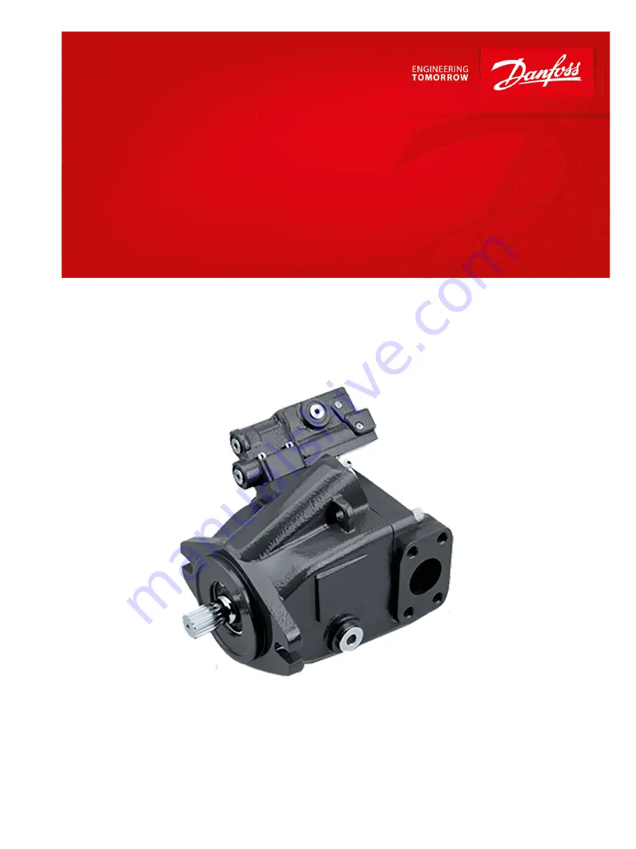
Repair Instructions
Axial Piston Open Circuit Pumps
Series 45 K2
powersolutions.danfoss.com
Page 1: ...Repair Instructions Axial Piston Open Circuit Pumps Series 45 K2 powersolutions danfoss com...
Page 2: ...Revision history Table of revisions Date Changed Rev April 2017 First edition 0101 Repair Instructions Series 45 Frame K2 Axial Piston Pumps 2 Danfoss April 2017 AX00000305en US0101...
Page 3: ...Drive Control 22 Shaft 23 Journal Bearing 23 Valve Plate 24 Housing 24 Shaft bearing kits 24 Servo piston 25 Endcap 25 Swashplate 25 Displacement Limiter 26 Displacement Limiter 26 Auxiliary Pad 26 Re...
Page 4: ...ble displacement open circuit pumps Remove the unit Prior to performing major repairs remove the unit from the vehicle machine Chock the wheels on the vehicle or lock the mechanism to inhibit movement...
Page 5: ...ome cleaning solvents are flammable To avoid possible fire do not use cleaning solvents in an area where a source of ignition may be present Fluid under pressure W Warning Escaping hydraulic fluid und...
Page 6: ...Mark orientation for reinstallation Parallelism specification Torque specification External hex head Press in press fit Internal hex head Pull out with tool press fit Torx head Cover splines with ins...
Page 7: ...120 The pad seal for an auxiliary A pad is reusable if undamaged 3 Remove the auxiliary pad screws J100 with an 8 mm internal hex wrench and remove the adapter J085 4 Remove and discard the O rings J0...
Page 8: ...Wrench size C300 5 mm internal hex Displacement limiter 1 Remove the adjustment seal nut L030 The L030 adjustment seal nut serves as a locking seal nut preventing the L040 screw from backing out 2 Re...
Page 9: ...g L010 with a 1 1 4 in wrench Discard the O ring L010A 2 Remove servo piston P025 from housing P109065 Endcap and valve plate 1 Remove the 4 endcap screws J030 using an 8 mm internal hex wrench Repair...
Page 10: ...er for more information B046 J030 J020 P109040 B070 J050 B020 J020 P109039 B010 J051 3 Slide the rear tapered roller bearing cone B020 from the bottom end of the shaft The bearing cup B010 may remain...
Page 11: ...re P109041 Input shaft and swashplate 1 Rotate the swashplate B040 until level with pump housing 2 Pull the shaft J010 from the shaft seal and bearing kit 3 Pull to remove the front tapered roller bea...
Page 12: ...B060 B050 B040 J010 B030 B025 B071 P109042 Shaft seal Repair Instructions Series 45 Frame K2 Axial Piston Pumps Disassembly 12 Danfoss April 2017 AX00000305en US0101...
Page 13: ...g so you do not lose or damage the spool PC only Remove the plug C103 and O ring C103A Discard the O ring Remove the screw C102 Remove the spool C132 Note the orientation of the spool for reinsertion...
Page 14: ...16 d C117 d C118 C133 C135 C134 C138 E101 180 dC138A RC132 dC103A d C106A d C104A d Electric control 1 Remove four screws C300 2 Remove the control and discard the four O rings C200 3 Remove set screw...
Page 15: ...mbly inspection and reassembly steps are the same as the steps in the previous topic Electric Controls This includes repair of the spools and plugs The solenoid C155 nut QC125 and O rings QC120 for th...
Page 16: ...mm internal hex 2 7 Nm 24 in lb Fan Drive Control Disassembly Use the wrench sizes and torques listed in the table 1 Remove four screws C300 2 Remove the control and discard the 4 interface O rings C2...
Page 17: ...7 mm exter hex 25 75 N m 19 lbf ft QC125 Coil plastic nut 26 mm 12 pt socket 3 5 N m 2 lbf ft C300 Screws 4 mm internal hex 6 5 N m 4 75 lbf ft Cylinder block Kit disassembly Disassemble the cylinder...
Page 18: ...refully release the pressure and remove the outer block spring washer block spring and inner block spring washer K042 from the cylinder block W Warning Risk of personal injury Compressing the block sp...
Page 19: ...mum slipper foot thickness P104 109E Ball Guide Slipper retainer and Hold Down Pins The ball guide should be free of nicks and scratches and should not be excessively scored Examine for discoloration...
Page 20: ...mm 0 71 in Inspect cylinder block C100 A flat to 0 002 mm flat to 0 000080 in P101 358 Control Carefully examine the PC and LS plug s for signs of wear Also check the small tip of the plug s for heavy...
Page 21: ...7 C116 C117 C118 i C133 C135 C134 iC138 C138A E101 181 iC132 iC138 e e e C104A C106A Electric control P108 668E G020 G030 C200 C102 C103 C132 C112 C104 C300 C125 C155 C150 C149 C154 C152 C151 C113 C11...
Page 22: ...wear Replace the spool if necessary 4 Check the spool for free smooth movement in housing bore 5 Check the orifices H030 and G020 for contamination and for cavitation damage 6 Check the solenoid cartr...
Page 23: ...with a non abrasive material Inspect the input splines or keyway block spines and output splines Replace the shaft if damaged Ensure that the shaft s splines are straight and lubricate the shaft with...
Page 24: ...arance should be flat and smooth on both the running face and the bottom surface The valve plate should be flat to 0 005 mm 0 0002 in convex A magnetic particle inspection is recommended to detect cra...
Page 25: ...ton L020 for wear on its end and for scratches along its cylindrical surface Replace if any wear is noticeable P025 P109045 Endcap 1 Inspect the endcap 2 Check and record the orientation of the timing...
Page 26: ...hplate if necessary P109047 B040 Displacement Limiter Inspect the displacement limiter screw threads L040 Ensure that the screw is not bent Also inspect the seal nut L030 for irregular wear Replace if...
Page 27: ...sing components B060 B050 B040 J010 B030 B025 B071 P109042 Bias Spring swashplate and Bearing Reinstall shaft bearing cup B060 and cone B050 Before replacing the bias spring B025 coat the curved surfa...
Page 28: ...the spiral retaining ring Release the pressure slowly after the retaining ring is installed 3 Turn the block over and install the retaining ring L Frame only K048 hold down pins K046 and ball guide K...
Page 29: ...with the split facing into or out of the slot in the valve plate The timing pin should be installed 3 6 0 25 mm 0 14 0 01 in above the endcap surface Apply a liberal amount of assembly grease to the b...
Page 30: ...the cup side facing the pump 3 Press the seal into the housing until it is deep enough to allow the retaining ring to be installed Press evenly to avoid binding and damaging the seal 4 Install snap ri...
Page 31: ...10 0 lbf ft C103 LS control optional Install the PC portion as described in PC control 1 Hold the control in a horizontal position Install the spherical end of the LS spool C112 into the LS bore see i...
Page 32: ...C105 t C105A tC106 tC102 C113 C115 C114 C117 d C116 d C117 d C118 C133 C135 C134 C138 E101 189 dC136 RC132 dC103A d dC106A C104A d Repair Instructions Series 45 Frame K2 Axial Piston Pumps Reassembly...
Page 33: ...O rings C200 in the recesses on the control housing 10 Install the control assembly onto the endcap using four screws C300 Torque screws in a criss cross pattern and re torque the first screw to ensur...
Page 34: ...to the endcap using the 4 screws C300 Torque at 5 4 to 7 5 N m 4 0 to 5 5 lbf ft using a criss cross pattern and retorque the first screw to ensure proper torque retention Install the control C200 C30...
Page 35: ...lbf ft If you have an auxiliary A pad install the J130 screws at 37 to 50 N m 27 to 37 lbf ft J140 J095 J100 J090 J085 J120 J110 J130 J140 J095 J100 J090 J085 J120 J110 J130 P109053 Install servo pist...
Page 36: ...bf ft 3 Turn adjustment seal nut L030A onto displacement limiter 4 Using a 19mm exter hex wrench torque the adjustment seal nut L030 to 54 N m 40 lbf ft Refer to Frame K2 Service Manual AX00000301 for...
Page 37: ...Repair Instructions Series 45 Frame K2 Axial Piston Pumps Danfoss April 2017 AX00000305en US0101 37...
Page 38: ...Repair Instructions Series 45 Frame K2 Axial Piston Pumps 38 Danfoss April 2017 AX00000305en US0101...
Page 39: ...Repair Instructions Series 45 Frame K2 Axial Piston Pumps Danfoss April 2017 AX00000305en US0101 39...
Page 40: ...r Solutions ApS Nordborgvej 81 DK 6430 Nordborg Denmark Phone 45 7488 2222 Danfoss Power Solutions US Company 2800 East 13th Street Ames IA 50010 USA Phone 1 515 239 6000 Danfoss Power Solutions Tradi...