background image

Instruction 

No: 

177R0091 

V0 

  Jan 

2009 

   Page 

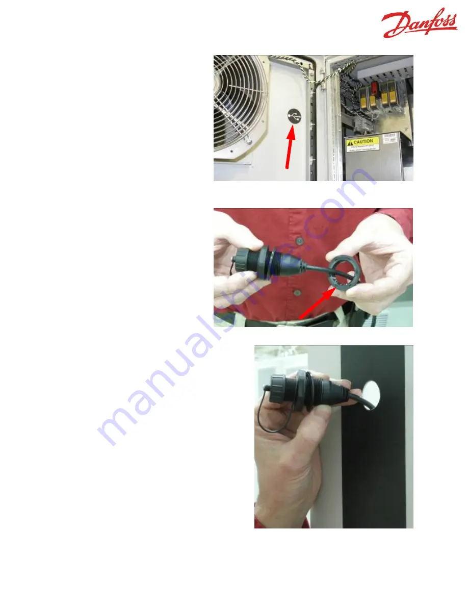
1.  Remove the label shown in Fig-

ure 2 to expose the USB feed-
through hole from the inside of 
the door. 

2.  Carefully cut through the exterior 

label to create a hole for the USB 
cable.  It is recommended that 
the hole be located by creating a 
hole in the label from the inside of 
the door, then cut through the 
decorative label from the outside 
to prevent the decorative label 
from separating from the door. 

Figure 3.  USB connector retaining nut. 

Figure 4.  Inserting USB cable into 
feed-through hole. 

Figure 2.  Location of USB feed-through hole. 

3.  Remove the retaining nut from 

the USB  cable.  See Figure 3. 


4.  Insert the USB cable into the door.  

The gasket should be located on the 
outside of the door.  See Figure 4. 


Summary of Contents for 176F1784

Page 1: ...s Instruction Sheet 177R0091 Kit Part Number 176F1784 The door on the rectifier section of F Frame VLTs are fitted with a feed through hole to accommodate a USB extension cord so that the controls can be accessed from a laptop computer without requiring access to the inside of the VLT With the rectifier door open the hole is located near the upper right corner of the door See Figures 1 and 2 The f...

Page 2: ...creating a hole in the label from the inside of the door then cut through the decorative label from the outside to prevent the decorative label from separating from the door Figure 3 USB connector retaining nut Figure 4 Inserting USB cable into feed through hole Figure 2 Location of USB feed through hole 3 Remove the retaining nut from the USB cable See Figure 3 4 Insert the USB cable into the doo...

Page 3: ...9 Page 3 5 Secure the USB connector onto the door by using the USB cable retaining nut from inside the door Tighten securely See Figures 5 and 6 Figure 5 Securing USB connector with retaining nut Figure 6 USB connector installed on door ...

Page 4: ...ure 8 Utilize cable ties to secure the USB cable to the LCP cable until the cable is inside the cable channel Figure 8 Routing of USB cable in rectifier cabinet 8 Route the USB cable from the cable channel to the control card as shown in Figure 9 Figure 9 USB cable 6 Remove the cable channel cover from the front of the cable chan nel to enable insertion of the USB cable See Figure 7 ...

Page 5: ...ct the USB cable to the control card as shown in Figure 10 10 Reinstall the cable channel cover as shown in Figure 11 The installation of the USB cable is now complete Figure 10 USB cable connected to control card Figure 11 Front cover of cable channel ...

Reviews: