background image


Manual page 5  

SETTING UP PROCEDURE 


Connect the two wires of the telephone line’s wall unit to the RJ-11 connector labeled LINE and connect the 
telephone appliance itself to the Hybrid’s RJ-11 connector labeled PHONE. Note that to originate calls, a 
local phone must be connected to the system. 
Now the hybrid is interfaced (fully balanced) between your telephone appliance and its connection to the 
outside world. The hybrid can now split the send and return signals.  
Now connect the hybrid’s balanced audio input (SEND on XLR male) to a (preferable) balanced mixer 
output of 4dBu. This output has to be the mix of all signals except the signal coming from the 
hybrid itself to avoid feedback.  An Aux. output will do or in broadcast mixers a clean-feed is the best. 
The balanced RECEIVE output of the Hybrid has to be connected to a line input of the mixing console. 
Note that this signal is NOT to be send to the output where the Hybrid’s input is connected to. So in case of 
use of an Aux send this local channel Aux send needs to be turned off. In case of use of a clean-feed 
buss, this input channel needs to be disconnected from the clean-feed buss. 
Turn the LC control fully counter clockwise and the HC control fully clockwise. 
Position RECEIVE and SEND controls in their mid position. 
If a local phone is connected, originate a call to a remote side. If no local phone is present, someone at a 
remote site must call you. When a call comes in the large ring BUTTON on the left side of the unit lights up 
green in the rhythm of the ring. When the line is picked up by pushing the button it turns into red. When it 
starts blinking red the line connection is lost. 
If you are at the originating side pres the CONNECT button to connect the Telephone Hybrid-2  to the phone 
line after the call has been established. The phone will be disconnected now. The caller will now hear the 
signal send to the Hybrid and the output of the Hybrid will present the callers signal only with the send 
signal heavily attenuated. 
 
To achieve the optimum attenuation you need to adjust the C and R balance first. 
This is how it is performed: 
 

1.  Check if the telephone connection is established and all connections to the mixing console are 

correctly wired. 

2.  Now activate a CUE/PFL/SOLO button of the mixing console channel where the return signal of the 

Hybrid is connected to. You will faintly hear the send signal coming out of the mixing console. 

3.  Adjust the R-Balance for minimum feed through of the mixers send signal. 
4.  Listen now which mini-dip switch gives a further reduction of the return signal. 
5.  Maybe it is good to re-adjust the R-balance after having selected another dip-switch. 
6.  Repeat steps 3 and 4 until no further improvement are achieved. 


Summary of Contents for Telephone Hybrid-2

Page 1: ...TELEPHONE HYBRID 2 USER MANUAL ...

Page 2: ... All functions are self explanatory and you will certainly appreciate the ergonomics of this design We are confident that you will be using the Telephone Hybrid for many years to come and wish you a lot of success with your operation With kind regards Duco de Rijk PRESIDENT D R ELECTRONICA WEESP B V Rijnkade 15B 1382 GS WEESP HOLLAND The Netherlands Phone 0294 418 014 Fax 0294 416 987 Website http...

Page 3: ... telephone line connection a handset connection and separate connectors for audio input and output from a broadcast mixer or other professional audio source A large proportion of D R hybrids are used in radio and television broadcasting applications allowing external callers to be connected to the studio mixing console Most of the other units are supplied to communication operations allowing extre...

Page 4: ...f the mixer SYSTEM DESCRIPTION A large ring button enables you to pick up the line from the unit itself or from your mixer when connected via its GPIO to the telephone Hybrid When a call comes in it lights up green in the rhythm of the ring When the line is picked up by pushing the button it turns into red When it starts blinking red the line connection is lost Both levels of receive and send can ...

Page 5: ...s in their mid position If a local phone is connected originate a call to aremote side If no local phone is present someone at a remote site must call you When a call comes in the large ring BUTTON on the left side of the unit lights up green in the rhythm of the ring When the line is picked up by pushing the button it turns into red When it starts blinking red the line connection is lost If you a...

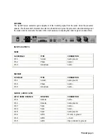
Page 6: ...aking the caller s signal is reduced then INPUTS OUTPUTS SEND XLR FEMALE TYPE CONNECTION Pin 1 Screen Audio ground Pin 2 Phase Audio Pin 3 Non phase Audio RECEIVE XLR MALE TYPE CONNECTION Pin 1 Screen Audio ground Pin 2 Phase Audio Pin 3 Non phase Audio SUB D 9 AUDIO GPIO GPIO SEND RECEIVE FUNCTION CONNECTION Pin 6 Receive Audio Pin 2 Receive Audio ground Pin 7 Send Audio Pin 3 Send Audio Pin 8 Se...

Page 7: ...e line In out Pin 4 n c LINE LINE RJ12 FUNCTION CONNECTION Pin 1 n c Pin 2 A telephone line In out Pin 3 B telephone line In out Pin 4 n c SPECIFICATIONS Audio Inputs SEND Impedance 10k Ohm electronically balanced Common mode rejection 40dB Maximum input level 26dBu Nominal input level 4 dBu Frequency response 20Hz 15kHz 3dB variable via HC and LC filters Connectors XLR type 3 pin female Gain rang...

Page 8: ...e impedance Nominally 600 ohm Telephone line impedance range 300 ohm to 1500 ohm Connectors XLR type 3 pin male Gain range send control 6dB to 20dB GENERAL Distortion Less than 0 1 0dBu out Power supply 115v 230 v AC 50 60Hz factory set NOT do this yourself Power consumption 10VA Maximum Dimensions 1 HE front panel 482x44mm Frame 430x41x175mm width x height x depth Weight 2 2 kg net excl packing I...

Page 9: ...ccordance with the following standards or standardized documents EN 50081 1 EN 55013 A 12 EN 50082 1 EN 55022 EN 60065 EN 61000 3 2 EN 55020 EN 61000 3 3 Supplementary Information The products herewith complies with the requirements of the EMC Directive 89 336 EWG and 73 23 EWG as amended by the CE Marking Directive 93 68 EEC 1993 Duco de Rijk August 2003 president D R Electronica Weesp b v Rijnka...

Page 10: ...ck But there is another thing to consider and it is resistance When the resistance in Ohms is high between two poles the current will be low and vice versa All three of these voltage current and resistance are important in determining the effect of an electrical shock However the severity of a shock primarily determined by the amount of current flowing through a person A person can feel a shock be...

Page 11: ...um it will create a very hazardous situation for the performing musician Always earth all your equipment by the grounding pin in your mains plug Hum loops should be only cured by proper wiring and isolation input output transformers Replace fuses always with the same type and rating after the equipment has been turned off and unplugged If the fuse blows again you have an equipment failure do not u...

Page 12: ...Manual page 12 TELEPHONE HYBRID 2 SERVICE MANUAL ...

Page 13: ......

Page 14: ......

Page 15: ...VC 1 0000 st 130 10700625 Kartelring M3 buitenvertand 2 0000 st 170 10450090 Knob SiF Rub Gry TPN110 006 13 4 0000 st 50 10600701 Mains inlet SKT MS3 FR MS3 1 0000 st 60 10600498 Mains lead 3 core Euroconnecto 1 0000 st 70 10700610 Moer M3 4 0000 st 200 10650383 Montagesnoer 1 5mm blauw 35 0000 cm 190 10650391 Montagesnoer 1 5mm bruin 35 0000 cm 210 10650388 Montagesnoer 1 5mm groen 30 0000 cm 10 ...

Page 16: ...st 760 10400292 Elco 100uF 25V rad R5 0 8 0000 st 770 10400293 Elco 220uF 63V radial R5 0 2 0000 st 780 10400297 Elco 1000uF 40V axial 30x12 5 2 0000 st 750 10400284 Elco 10uF 50V radial R5 0 1 0000 st 790 10600505 Header 2p pin 0º sngl 1 0000 st 830 10600474 Header 3p 0º 3 96 1 0000 st 910 10600513 Header 5P Lock 0º 2 54 2 0000 st 800 10600514 Header 5P Lock 90º 2 54 1 0000 st 950 10600506 Header...

Page 17: ...k 5 1 4W 2 0000 st 350 10350859 Resistor 24k3 1 1 4W 1 0000 st 360 10350861 Resistor 28k7 1 1 4W 1 0000 st 140 10350713 Resistor 47E 5 1 4W 8 0000 st 370 10350749 Resistor 47K 5 1 4W 1 0000 st 380 10350751 Resistor 68k 5 1 4W 1 0000 st 150 10350717 Resistor 100E 5 1 4W 4 0000 st 390 10350758 Resistor 270k 5 1 4W 1 0000 st 400 10350760 Resistor 390k 5 1 4W 1 0000 st 160 10350725 Resistor 470E 5 1 4...

Reviews: