background image


PART#: 212-2014-K 

July 30th, 2019


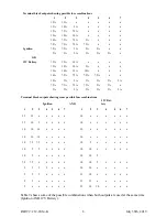
Table 2 shows some of the possible combinations when both outputs are used at the same time 
(Ignition AND 12V Battery).  

Terminal block outputs showing some possible fuse combinations


Ignition


AND


12V Bat-
tery


1


2


3


4


5


6


7


1


2


3


4


5


6


7


15 

15 

   10 

15 

10 

   10 

10 

10 

10 

   10 

10 

10 

10 

   10 

10 

7.5  7.5 

   10 

10 

   10 

10 

10 

   10 

10 


7.5 

7.5 

   10 

10 

   10 

10 


   15 

10 

   15 

15 

   15 

10 

10 

Terminal block outputs showing possible fuse combinations


1


2


3


4


5


6


7


15A 

15A 


15A 

10A 

5A 


15A 

7.5A 

7.5A 


10A 

10A 

10A 


10A 

7.5A 

7.5A 

5A 


7.5A 

7.5A 

7.5A 

7.5A 

 Ignition 

7.5A 

7.5A 

5A 

5A 

5A 


5A 

5A 

5A 

5A 

5A 

5A 

OR


12V Battery


15A 

15A 

10A 


15A 

10A 

10A 

5A 


10A 

10A 

10A 

10A 


10A 

7.5A 

7.5A 

7.5A 

7.5A 


10A 

5A 

5A 

5A 

5A 

5A 

5A 


7.5A 

7.5A 

7.5A 

7.5A 

5A 

5A 


5A 

5A 

5A 

5A 

5A 

5A 

5A 

Summary of Contents for PDU14-K

Page 1: ...tion Operations Manual Table of Contents Applicable Models 2 Introduction 2 General Warnings 2 Unpacking Pre Installation Check 3 Installation Mounting 3 Wiring and Setup Instructions 4 Maintenance 8 Troubleshooting 8 Parts List 10 Product Specifications 11 Warranty 12 PDU14 ...

Page 2: ...and maintenance Read the manufactures instruc tions before installing and follow all recommendations 3 When in use the operator must ensure that the warning signal is visible and not obstructed by vehicle components i e open trunk lid people or other obstructions 4 This device is intended for use by authorized personnel only The user is responsibility to ensure that all local state provincial and ...

Page 3: ... The Power Distribution Unit PDU is shipped pre assembled and factory tested All necessary hardware for standard installation is included Remove all components from the shipping carton Use this pre installation check list to verify your unit 1 Confirm contents with the packing slip 2 Examine unit for damaged in transit i e scratches broken or bent connect ors etc Report any damage to the carrier i...

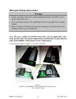
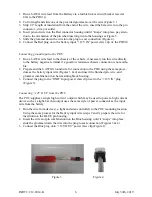
Page 4: ...should be minimized and made in a fashion so as to protect from cor rosion to reduce loss of conductivity Warning Note The exact number of available connections varies by application refer to the specifications and typical output fusing combinations to ensure that the safety and reliability of this product is not compromised Connecting the Battery Input 12V IN to the PDU Figure 1 End Views of the ...

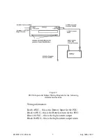
Page 5: ...Wiring Diagram for the following detailed instructions Wiring information Red 6 AWG this is the Battery Input for the PDU Black 6 AWG this is the Battery return for the PDU Blue 10 AWG this is the high current output Black 10AWG this is the high current output return ...

Page 6: ...low resistance chassis connection is not availa ble 2 Prepare and the 6 AWG Ground wire for connection to the PDU using the same proce dure as the battery input wire Figures 3 4 and insert the finished pin wire and grommet combination into he remaining black housing 3 Connect the plug to the GND Input power claw clip next to the 12V IN plug Figure 3 Connecting 12V OUT from the PDU The PDU supplies...

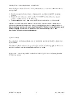
Page 7: ...via the terminals on the chassis These terminal connections should be made using good industry practice ensuring no loose or frayed wire be present at each screw down terminal We further recommend using a good quality crimping tool and wire terminals to secure the wire and provide a solid screw down connection at the terminal block Application Brief The connections and fusing configurations are in...

Page 8: ...5 5 x x x x 10 10 x x x x x 10 5 x x x x x 10 10 5 7 5 7 5 x x x x x 10 10 5 x x x x 5 5 5 5 x x x 10 10 x x x x 5 5 5 x x x x 15 10 x x x x x 5 5 x x x x x 15 15 x x x x x 5 x x x x x x 15 10 10 x x x x Terminal block outputs showing possible fuse combinations 1 2 3 4 5 6 7 15A 15A x x x x x 15A 10A 5A x x x x 15A 7 5A 7 5A x x x x 10A 10A 10A x x x x 10A 7 5A 7 5A 5A x x x 7 5A 7 5A 7 5A 7 5A x ...

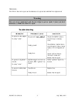
Page 9: ...s Ground connection Return Unit for repair No power to Ignition circuits No relay click Ignition trigger wire not con nected to PDU ignition ter minal Verify ignition input con nection No power to Individual Circuits Fuse Blown Faulty Circuit Replace fuse Return Unit for repair Troubleshooting There are no user maintained parts Do not attempt to open or repair Contact your local distributor or D R...

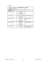
Page 10: ...NG GROUND plugs 196 0002 4 PIN 75A 6 AWG Pins for INPUT and OUTPUT plugs PART NUMBER QUAN TITY DESCRIPTION NOTES Standard Parts PDU 14 1 POWER DISTRIBUTION UNIT 201 0012 1 PLUG 75A RED HOUSING Power INPUT plug 201 0046 1 PLUG 75A BLUE HOUSING Power OUTPUT plug Parts ...

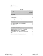
Page 11: ...gnition Control Input 1 Power Output 10 AWG 20A Max 12V fused at 30A 1 10 AWG Ground 1 Terminal Block Power Outputs Ignition Controlled Power 40A relay all com bined output power not exceed 30A max 7 Continuous Power the total current not to exceed 40A 7 Ground return path for the Output terminal blocks the total return current not exceed 40A 6 ...

Page 12: ... for removal or installation Lamps flash tubes batteries or other items considered consumables are not covered under warranty This warranty is in lieu of all other express warranties D R Electronics makes no war ranties expressed or implied other than the express warranties contained herein WARRANTY PRODUCT RETURN POLICY In order to provide you with faster service product returns for repair or rep...

Reviews: