212-0024-6SS
5
July 30th, 2019
Mechanical Installation
NOTE the PDU is not weather tight. Do not mount it in the engine compartment, on the exterior of the ve-
hicle or an area where there is moisture, dirt or other contaminants. Ensure that the mounting location is
flat and the device is secured to solid vehicle body parts.
1.
Determine an appropriate mounting location.
2.
Confirm there is adequate access and clearance for the wiring and all connections.
3.
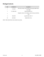
Secure the PDU with 4 self-tapping mounting screws (not supplied).
Electrical Installation
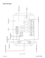
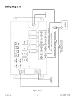
12V Battery
Using appropriate size wire connect to the positive battery terminal fuse at the battery side with a 100A fuse
or circuit breaker.
Ground
Using appropriate size wire connect to the negative battery terminal or a suitable chassis ground.
Ignition Sense
Connect this terminal to the vehicle ignition switch using 18 gauge wire.
Battery Sense
Connect this terminal directly to the positive of the battery using a 18 gauge wire fused with a 5A fuse. This
connection must be made in order for the PDU-6SS to work.
Ground Sense
Connect this terminal to the negative side of the battery or a suitable chassis ground. This connection must
be made in order for the PDU 6SS to work.
Outputs
The PDU offers the following outputs. (1) 25A in group 1, (2) 15A in group 1, (2) 15A in group 2 and (1) direct-
ly from the battery (this output is available even when the PDU is dormant).
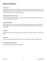
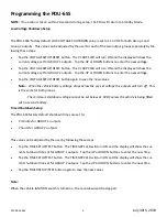
NOTE: When the IGNITION is OFF and the main +12V power input is disconnected, the DISPLAY will
stay ON until both timers expire or the BATTERY SENSE input is disconnected.


