background image


212-0024-SS 

July 30th, 2019


Warning 

1.  The use of emergency warning devices does not ensure the safety of the operator. The operator is 

responsible to ensure safe operation of the vehicle regardless of whether the warning device is  in 

operation or not 

2.  The effectiveness of this or any warning device is highly dependent on proper installation and 

maintenance. Read the manufactures instructions before installing and follow all recommenda-

tions.  

3.  When in use the operator must ensure that the warning signal is visible and not obstructed by vehi-

cle components (i.e. open trunk lid), people or other obstructions 

4.  This device is intended for use by authorized personnel only.  It is the responsibility of the user to 

ensure that all local, state, provincial and federal laws are being complied with. D&R assumes no 

liability for any loss resulting from the use of this device.  

5.  The device must be installed so as not to reduce the output performance of vehicle systems.  
6.  Placement of control switches must be so as to provide convenient reach for the operator without 

loosing eye contact with the road. 

7.  Emergency warning devices require high electrical voltages and/or currents. Properly connect and 

ground all circuits. Shorting or improper grounding of this device may caused personal injuring, ve-

hicle damage and/or device damage. 

8.  All operators should be properly trained in the operation of this device to ensure both operator and 

public safety  

9.  Any device used inside a vehicle, may cause severe personal injury  if not properly mounted and 

secured. Objects used in the vehicle may become airborne during a collision or other sudden chang-

es in vehicle speed or direction, such as braking,  acceleration or turns.    

10. Be sure to mount unit through the steel of the vehicle. Avoid mounting through plastic or other non

-structural materials.  

11. POINT OF INSTALLATION MUST NOT INTERFERE WITH DEPLOYMENT OF VEHICLE AIR BAGS.  
12. D&R Electronics recommends that this and any of our other products be installed by qualified per-

sonnel. 

13. Good wiring practices and thorough knowledge of vehicle power systems is required by the installer 

of this and any other product. 

14. Looms, grommets, cable ties or other installation hardware should be used to anchor and protect 

wiring. 

15. All wire sizes must meet the minimum sizes specified by the manufacturer.  
16. Splices should be minimized and made in a fashion so as to protect from moisture which could 

cause corrosion thereby reducing conductivity.  

17. The exact number of available connections varies by application.  Refer to the specifications and 

typical output fusing combinations to ensure that the safety and reliability of this product is not 

compromised. 

Warning 


Maintenance 

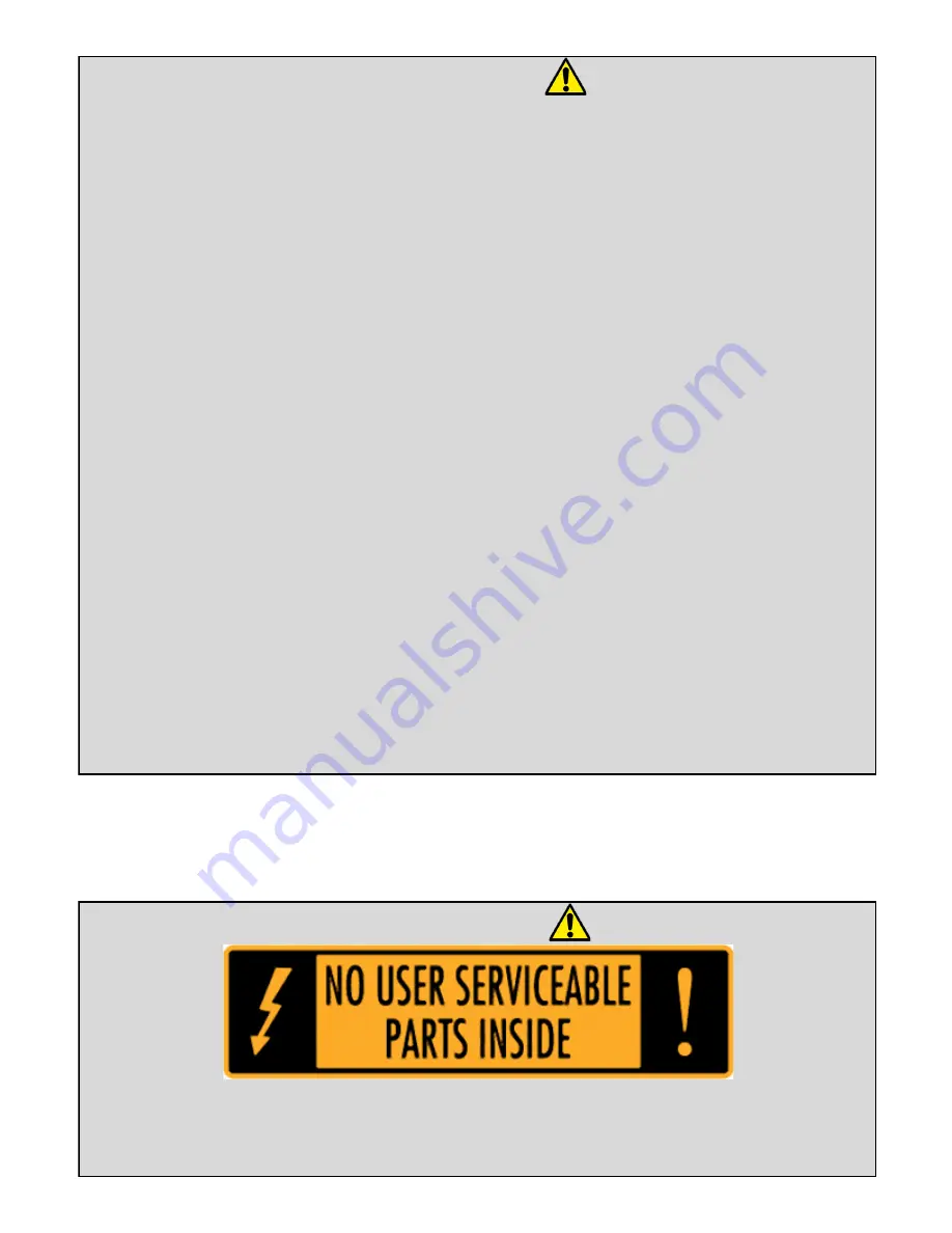
The PDU-16SS does not require user maintenance except for the individual fuse replacements. 

Do not attempt to open or repair. 

Contact your local distributor or D&R Electronics for repair. 

Summary of Contents for PDU-16SS

Page 1: ...SS Table of Contents Product Overview 2 Introduction Features Technical Specifications 3 Warnings 4 Installation 5 Wiring Diagram 6 Wire Gauge Size Tables 7 Modes of Operation 8 Programming Low Voltage Shutdown and Timed Shutdown 9 Package Contents 10 Warranty and Product Return Policy 12 ...

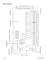
Page 2: ...212 0024 SS 2 July 30th 2019 Product Overview Figure 1 PDU 16SS ...

Page 3: ...Features Programmable Low Battery Voltage Shutdown Programmable Timed Shutdown Vehicle Battery Voltage Monitoring Each output has an LED fuse status indicator Standby Mode Timed Shutdown Mode Test Mode Reset Mode 16 Outputs Technical Specifications Voltage Range 11 18 VDC Maximum Current Load 15A per output fused at 20A 30A per heavy duty output fused at 50A 100A total maximum current per PDU Stan...

Page 4: ...hould be properly trained in the operation of this device to ensure both operator and public safety 9 Any device used inside a vehicle may cause severe personal injury if not properly mounted and secured Objects used in the vehicle may become airborne during a collision or other sudden chang es in vehicle speed or direction such as braking acceleration or turns 10 Be sure to mount unit through the...

Page 5: ...t the battery side with 100A fuse or a circuit breaker Ground Using appropriate size wire connect to the negative battery terminal or a suitable chassis ground Ignition Sense Connect this terminal to the vehicle ignition switch using 18 gauge wire Battery Sense Connect this terminal directly to the positive of the battery using a 18 gauge wire fused with a 5A fuse This connection must be made in o...

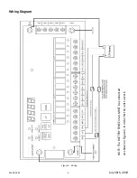
Page 6: ...212 0024 SS 6 July 30th 2019 Figure 2 Wiring NOTE The BATTERY SENSE lines MUST be connected As shown in Figure 2 in order for the unit to work Wiring Diagram ...

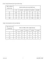
Page 7: ...ngth 3 drop 5 ft 5 10 ft 10 15 ft 15 20 ft 25 30 ft 25 10 6 6 4 2 50 6 4 2 2 0 75 6 2 1 0 3 0 100 4 2 0 2 0 4 0 Table 2 Recommended Circuit Load Wire Size Max Total Load Current Amps Wire Size AWG vs Wire Length 3 drop 1 5 ft 5 10 ft 10 15 ft 15 20 ft 25 30 ft 5 18 18 18 16 14 10 18 16 14 14 12 15 18 14 12 12 10 20 16 14 12 10 8 ...

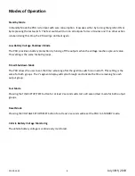
Page 8: ...voltage reaches a pre set value This setting is the same for both groups Timed Shutdown Mode The PDU allows the user to set the time remaining after the ignition switch is turned off This setting is the same for both groups The 7 segment display will cycle through and indicate the time remaining for each output group Test Mode Pressing the TIME SETUP TEST button for at least 2 seconds will start a...

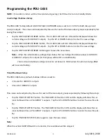
Page 9: ...he vehicle battery voltage drops below the Low Voltage Shutdown values for GROUP 1 or GROUP 2 outputs the outputs for that group will be OFF unconditionally The minimum shutdown voltage cannot be set below 11 5VDC unless the vehicle is being fitted with a second battery Timed Shutdown Setup The PDU 16SS factory default shutdown times are set to 2 minutes for GROUP 1 outputs 2 hours for GROUP 2 out...

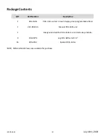
Page 10: ...6SS unit w 16 out display dual programmable timer 1 212 0024 SS Manual PDU 16SS unit 1 Designator sheet for PDU 16SS to record all setup installa 4 196 0070 Lug LD 6 AWG stud 1 4 16 205 0052 Spade 8 16 14 Ga Package Contents NOTE MINI and MAXI fuses are available for purchase ...

Page 11: ...212 0024 SS 11 July 30th 2019 NOTES ...

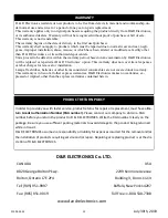
Page 12: ...or removal or installation Lamps flash tubes batteries or other items considered consumables are not covered under warranty This warranty is in lieu of all other express warranties D R Electronics makes no warranties ex pressed or implied other than the express warranties contained herein WARRANTY PRODUCT RETURN POLICY In order to provide you with faster service product returns for repair or repla...

Reviews: