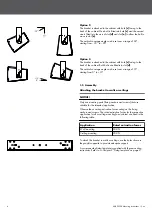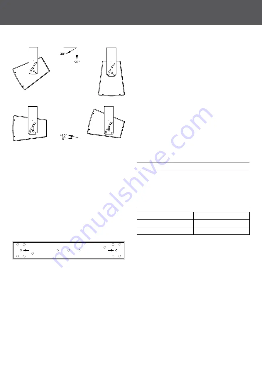
Option 2
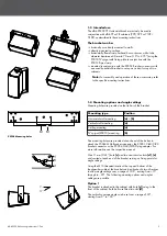
The bracket is attached to the cabinet with hole
[c] facing to the
back of the cabinet. One bolt is fitted into hole
[c] and the second
one is fitted into the axis of slot
[d] and slot [e] to allow the bolt to
move in slot
[e].
The vertical coverage angle can be set over a range of 60°,
starting from –30° to –90°.
Option 3
The bracket is attached to the cabinet with hole
[c] facing to the
back of the cabinet. Both bolts are fitted into slot
[d].
The vertical coverage angle can be set over a range of 15°,
starting from 0° to +15°.
1.5 Assembly
Attaching the bracket to walls or ceilings
NOTICE!
Only use mounting parts (fixing anchors and screws) that are
suitable for the intended application.
Observe the occurring extraction forces acting on the fixing
anchors and screws. The rated extraction forces for the respective
application (wall or ceiling mounting) and cabinet are listed in the
following table.
Application
Rated extraction forces
Wall mounting
300 N
Ceiling mounting
200 N
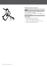
To attach the bracket to walls or ceilings, use the holes shown in
the graphic opposite to provide adequate support.
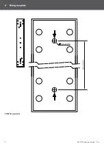
A corresponding fixing template is supplied with these mounting
instructions. Refer to
Chapter 2 "Fixing template" on page 8.
d&b Z5398 Mounting instructions 1.3 en
6
Summary of Contents for Z5398
Page 1: ...Z Z5398 Mounting instructions 1 3 en ...
Page 8: ...Z5398 Fixing template 2 Fixing template d b Z5398 Mounting instructions 1 3 en 8 ...
Page 10: ...Built in dimensions Z5010 Z5012 Assembly d b Z5398 Mounting instructions 1 3 en 10 ...
Page 12: ...D2818 EN 01 04 2020 d b audiotechnik GmbH Co KG www dbaudio com ...


