

KIT
2
1
★
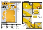
Assenbly symbol guide
Photos shown here just for reference, the product you received maybe slightly
differ from the photos due to continuous improvement on products.
Ensure free rotation
Use medium CA
Use a pencil
Use thin CA
Push tightly
Use hobby knife with
OIL
A
pply Oil
Fully Tighten
Apply threadlock
Assemble right
and left
Glue with epoxy
adhesive
Epoxy glue
Repeat multiple times
x2
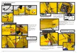
01
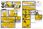
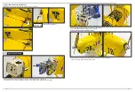
Assemble the Landing Gear
A
B1
B2
C
D
E
F1
F2
F3
F4
G1
G2
H
I1 I2
I3
J
K
L
M
N
O
P
Q
01-1
01-2
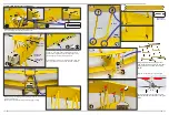
01-3
01-4
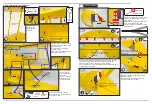
01-5
I1
I4
I4
I3
I2
I3
I4
Self-locking nut+Screw
Nut
Nut
Nut
Nut
Here please use
same installation
way for left and
right.
M3*18mm
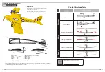
Q: Screw
Link Rod
Pulling Wire
Connectors
P: Instruments Panel
O:
Tail Wheel Set
N: Fortified Wooden piece,
Aluminum Sheet
M: Windshield
L: Rubber Strip
K: Magic Tape
J: Engine Seat
I1-3: Landing Gear Set
H: Cowling
G1-2: Wheels and Bearing
F1-4: Holder
E: Wing Connectors
D:
V
ertical Tail
C: Horizontal Tail
B1-2: Upper Wing and
Lower Wing
A: Fuselage


