


Terminal
block
Red or
Black
Red or
Black
Neutral
terminal
Ground plate
(grounding to
range)
Ground
screw
White
Green
or Bare
After–Power Cord
INSTALLATION INSTRUCTIONS
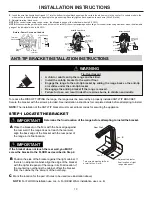
STEP 1 LOCATE THE BRACKET
Determine the
fi
nal location of the range before attempting to install the bracket.
Place the bracket on the
fl
oor with the back edge against
the rear wall. If the range does not reach the rear wall,
align the back edge of the bracket with the rear panel of
the range in its
fi
nal location.
If the bracket does not touch the rear wall, you MUST
screw the bracket to the FLOOR as described in Step 2.
Position the side of the bracket against the right cabinet. If
there is no adjacent cabinet, align the edge of the bracket
with the right side panel of the range in its
fi
nal location. If
the countertop overhangs the cabinet, offset the bracket
from the cabinet by the amount of the overhang.
A
B
Mark the location for the pair of holes to be used (see illustration above).
NOTE:
For FLOOR installation use Loc. A. For REAR WALL installation use Loc. B.
C
Rear Wall
Loc. B
Loc. A
Two screws must enter floor
or wall at Loc. A or B.
Adjacent cabinet or
final location of right
range side panel.
IMPORTANT
IMPORTANT
ANTI-TIP BRACKET INSTALLATION INSTRUCTIONS
To reduce the RISK OF TIPPING the range, the range must be secured by a properly installed ANTI-TIP BRACKET.
Secure the bracket with the screws provided. See installation instructions for complete details before attempting to install.
NOTE:
The installation of the ANTI-TIP bracket must meet all local codes for securing the appliance.
WARNING
Tip-Over Hazard
• A child or adult can tip the range and be killed.
• Install the anti-tip bracket to the wall or
fl
oor.
• Engage the range to the anti-tip bracket by sliding the range back so the anti-tip
arm slides under the anti-tip bracket.
• Re-engage the anti-tip bracket if the range is moved.
• Failure to do so can result in death or serious burns to children and adults.
Before–Power Cord and Conduit
Terminal
block
Neutral
terminal
Ground
strap
Ground strap
or
st
After–Conduit
Terminal
block
Ground plate
(grounding to
range)
Wire
tips
Ground
Red or
Red or
Black
White
Green
E.
Insert the wire tips (insulation stripped ⅝”) into the bottom terminal block openings. Be certain the white wire is in the center. On certain models, the
wire must be inserted through an opening in the ground strap. Securely tighten each screw onto each wire (35 to 50 in-lbs).
F.
Reinstall terminal block cover.
NOTE:
For conduit wires using copper wires, the allowable gauge of the individual wires is 6-8 AWG.
NOTE:
Aluminum building wire may be used but it must be rated for the correct amperage and voltage. For conduit wires using aluminum wires, the allowable
gauge of the individual wires is 4-8 AWG.
19
Summary of Contents for DER244BSS
Page 47: ...NOTE 45 ...
Page 48: ...NOTE 46 ...