background image

8

i Po r t   I W- 2 0 / I W- 2 1 / I W- 2 2

I n s t r u c t i o n   M a nu a l

IMPORTANT: Do 

not

install the iPort wall plate in the same elec-

trical box as AC house wiring, a light switch, or any other high-
voltage device or control. The wall plate can share gang boxes
with other iPort wall plates or with controls such as A/B speaker
switches, infrared receivers, and volume controls, if these other
devices are rated as Class 2 devices according to the National
Electrical Code.

5. Use a stereo RCA audio cable to connect the wall plate’s A

UDIO

connectors to a source input on the local-zone audio system, as
shown in 

Figure 4

, page 7.

6. Insert the iPort utility box into the opening in the wall.

• First insert the top edge into the opening, then rotate the bottom

edge into the opening.

Note: The Roto-Lock system can accommodate a maximum
wall material thickness of 1

3

/

8

”.

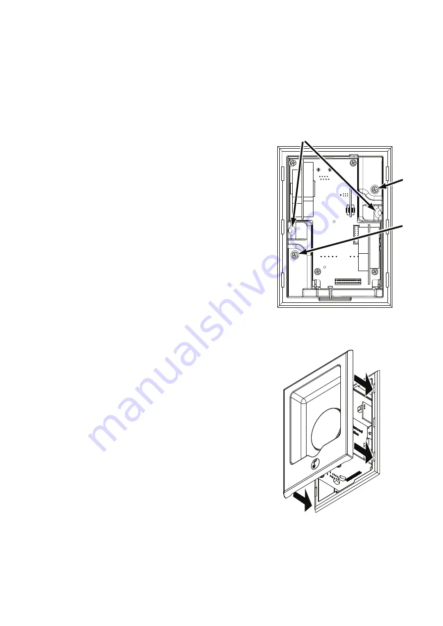
7. Hand-tighten the two Roto-Lock screws on the iPort utility box 

as shown in 

Figure 5

. The Roto-Lock clamps will automatically rotate

into position behind the wall and begin clamping the iPort.

• When you notice resistance on the two screws, the iPort has been

clamped successfully.

IMPORTANT: NEVER over-tighten the Roto-Lock screws.

8. If there is a wall stud up against one side of the utility box that 

prevents one Roto-Lock clamp from operating, secure the box by
hand-driving a 1½” #6 drywall screw (not provided) through the
angled hole on that side of the chassis and into the wall stud. 
See 

Figure 5

IMPORTANT: Do not over-tighten the drywall screw.

9. Attach the iPort face to the utility box as shown in 

Figure 6

. Slide the

face all the way into the box until it fits snugly into place.

10. Plug the included DC power supply into the 

Power

connector on

the wall plate and into a wall outlet, as shown in 

Figure 4

, page 7.

Roto-Lock
Screw

Roto-Lock
Screw

If mounted next to

a stud, drive a 1½”

#6 drywall screw

here

Figure 5: Attaching the Utility Box to a Wall

Figure 6: Attaching the Face
to the Utility Box

All manuals and user guides at all-guides.com

Summary of Contents for iPort IW-20

Page 1: ...Instruction Manual IW 20 IW 21 IW 22 All manuals and user guides at all guides com a l l g u i d e s c o m...

Page 2: ...al IW 21 System Capabilities Delivers local zone unbalanced audio up to 30 feet from the iPort Optional Balanced Audio Upgrade Kit part number 70130 required for distributed audio distances up to 500...

Page 3: ...audio functions when in general control mode Optional iPort remote available part number 70030 black 70032 white Integrated RS 232 control enables two way communication including iPod program metadat...

Page 4: ...Port in a location that is in direct sunlight a portion of the day as it can interfere with IR operation Selectable Features IW 21 and IW 22 only IMPORTANT Before installing the iPort you need to sele...

Page 5: ...deo wall plates use the included 5 foot RJ 45 to female RCA cable and require a male to male RCA cable not included Balanced video wall plates require that the installer make a Cat5 RJ 45 cable as des...

Page 6: ...steps 2 7 with a new RJ 45 connector Installation Preparation all models The iPort features an integral Roto Lock mounting system for quick mounting directly into existing walls Once the hole is cut a...

Page 7: ...page 6 The audio Cat5 RJ 45 cable pin assignment is 3 Plug the Cat5 cable into the AUDIO connector on the iPort and the RJ 45 jack on the wall plate as shown in Figure 4 4 Install the wall plate into...

Page 8: ...tility box as shown in Figure 5 The Roto Lock clamps will automatically rotate into position behind the wall and begin clamping the iPort When you notice resistance on the two screws the iPort has bee...

Page 9: ...o Cat5 RJ 45 cable pin assignment is 9 To Video Wall Plate Supplemental Power GND 15V GND 15V VIDEO RJ 45 Video Connector Supplemental Power Connector not used RJ 45 Audio Connector To RCA Connector o...

Page 10: ...can accommodate a maximum wall material thickness of 13 8 9 Hand tighten the two Roto Lock screws on the iPort utility box as shown in Figure 5 on page 8 The Roto Lock clamps will automatically rotat...

Page 11: ...e way into their connectors Installing the Balanced Audio Circuit Card 1 Locate the balanced audio PCB Connector and BALANCED UNBALANCED audio switch on the iPort backplane circuit board see Figure 8a...

Page 12: ...dard male to male RCA cable through the wall from the iPort location to the unbalanced video wall plate location as shown in Figure 10 page 13 The balanced audio wall plate can be located up to 500 fe...

Page 13: ...RJ 45 Video Connector RJ 45 Audio Connector To RJ 45 Connector on Wall Plate Rear To AUDIO Connectors To RS 232 Connector To VIDEO Connector To Composite Video Input To PWR Connector STEREO RCA CABLE...

Page 14: ...a stereo RCA audio cable to connect the balanced audio wall plate s AUDIO connectors to a source input on the audio system as shown in Figure 10 page 13 9 For IR control systems Use a 3 5mm cable mon...

Page 15: ...see Selectable Features page 4 and attach the iPort face to the utility box as shown in Figure 6 page 8 Slide the face all the way into the box until it fits snugly into place 16 Plug the included DC...

Page 16: ...at and shuffle Extensive long distance control of the iPod iPhone from a compatible IR control system is also available through the IR connector on the balanced audio wall plate Go to iportmusic com f...

Page 17: ...rom the iPort the indicator illuminates DIM for 2 minutes then turns OFF The user can change these settings to any of three illumination levels bright medium and dim via RS 232 or the iPort remote Alw...

Page 18: ...ate to state Some states do not allow the exclusion of implied warranties or limitations of remedies so the above exclusions and limitations may not apply If your state does not allow disclaimer of im...

Page 19: ...19 iPort IW 20 IW 21 IW 22 Instruction Manual Notes All manuals and user guides at all guides com...

Page 20: ...Lock are registered trademarks of Dana Innovations iPod and iPhone are trademarks or registered trademarks of Apple Inc Due to continuous product improvement all specifications are subject to change w...

Reviews: