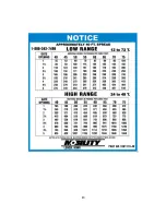
An operational characteristic of this type of machine is the possibility of overloading the distributors
at high rates of application. Such an overload results in an alteration of the spread pattern to a narrower
swath with heavier application at the center. This can be avoided by reducing speed when using high
application rates. MOBILITY DISTRIBUTORS ARE DESIGNED FOR A MAXIMUM APPLICATION
RATE OF 1500 POUNDS PER MINUTE OF AVERAGE 60 POUND PER CUBIC FOOT MATERIAL.
Caution: Be extra careful to check your spread pattern when using high application rates. Adjust your
driving pattern to the actual delivered spread swath, the adjustment of the machine, and the material be
-
ing used. Recommended ground or travel speed for most application rates (up to 700 pounds per acre) is
8 mph. When application rates are in excess of 700 pounds per acre, the ground speed should be pro
-
portionately reduced, (for example, at 1400 pounds per acre, maximum ground speed should be 4 mph.)
We recommend that for very high application rates, to insure uniformity of application, that two lighter
application passes be made preferably placing your second pass over the lap lines of the first pass. This
also is recommended practice when spreading under very windy conditions or with a material that segre
-
gates easily. If your effective spread pattern is more than 50 feet wide the Metering Gate setting should
be increased proportionately, according to the percentage of your spread width in excess of 50 feet. The
gate setting should likewise be decreased if your effective spread pattern is less than 50 feet. EXAMPLE:
60 foot effective spread width—increase gate setting from Spread Chart by 20%; 40 foot effective spread
pattern width—decrease your gate setting from Spread Chart setting by 20%. Your spread pattern can be
checked accurately and visually on a freshly worked, level area of ground. Such an area is also ideally
suited to adjusting and fine tuning your machine. The following diagram graphically illustrates a typical
spread pattern.
Note on the illustration below that the lap point occurs at the point where the application rate is one-
half of the spread chart rate. The profile of the spread pattern tapers at both edges and has a wide uniform
area in the center. By careful attention to the lap point during application, a very uniform and even spread
rate can be attained. The Mobility Spreaders have been designed to provide this good and uniform ta-
pered profile to make spread width less critical. However, excessive or insufficient overlap of passes will
result in a poor application pattern in the lap area of the total spread pattern. If you can attain this spread
pattern and pay careful attention to the lap points, the dotted line on the illustration will represent your
actual overall spread pattern.
EFFECTIVE SPREAD
PATTERN WIDTH
OVERLAP
SINGLE PASS
SPREAD PATTERN
SPREAD CHART
APPLICATION
RATE
LAP POINT
RESULTING OVERALL
SPREAD PATTERN
SPREAD PATTERN DETAILS
10
Summary of Contents for Mobility 100
Page 15: ...13 ...
Page 16: ...14 ...
Page 32: ...VARIABLE RATE CONTROL ELECTRICAL PLAN 30 ...
Page 38: ......


