background image


Xtium2-CXP PX8 User's Manual 

Technical Specifications  

  121 

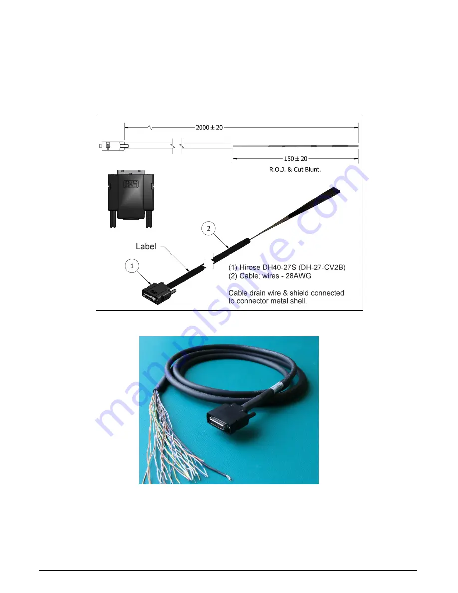
DH40-27S Cable to Blunt End (OR-YXCC-27BE2M1, Rev B1) 

Cable assembly consists of a 2000 mm (~6 ft.) blunt end cable to mate to Xtium external 

connector J7. Note: The applicable wiring color-code table is included with the printed Product 

Notice shipped with the cable package — no other wiring table should be used.  
Important: The older cable part number OR-YXCC-27BE2M0 (rev.3) is obsolete. Do not use with 

any Xtium series boards.  


Figure 54: DH60-27P Cable No. OR-YXCC-27BE2M1 Detail 


Figure 55: Photo of cable OR-YXCC-27BE2M1  


Summary of Contents for Xtium2-CXP PX8 Quad

Page 1: ...Xtium2 CXP PX8 User s Manual Edition 1 00 P N OC A8XM PX8U0 www teledynedalsa com sensors cameras frame grabbers processors software vision solutions ...

Page 2: ...ft is a registered trademark Windows Windows 10 are trademarks of Microsoft Corporation All other trademarks or intellectual property mentioned herein belongs to their respective owners Edition 1 00 released on October 2 2020 Document Number OC A8XM PX8U0 About Teledyne DALSA Teledyne DALSA is an international high performance semiconductor and Electronics Company that designs develops manufacture...

Page 3: ...r from the Start Menu 20 REQUIREMENTS FOR A SILENT INSTALL 21 Silent Mode Installation 21 Creating a Response File 21 Running a Silent Mode Installation 21 Silent Mode Uninstall 22 Creating a Response File 22 Running a Silent Mode Uninstall 22 Silent Mode Installation Return Code 22 Installation Setup with CorAppLauncher exe 22 Custom Driver Installation using install ini 23 Creating the install i...

Page 4: ...45 Symptoms PoCXP does not power the camera 45 Over current protection circuit is tripped 46 To clear the TRIP condition of the Xtium2 CXP PX8 over current circuit 47 CAMEXPERT QUICK START 48 INTERFACING CXP CAMERAS WITH CAMEXPERT 48 CamExpert Example with a Monochrome Camera 48 CAMEXPERT DEMONSTRATION AND TEST TOOLS 50 Camera Types Files 50 Overview of Sapera Acquisition Parameter Files ccf or cc...

Page 5: ...n Lists 83 Flat Field Correction Sets 83 Xtium2 CXP PX8 specific limitations 83 Programming the sets 84 XTIUM2 CXP PX8 SUPPORTED PARAMETERS 85 Camera Related Capabilities 85 Camera Related Parameters 85 VIC Related Parameters 86 ACQ Related Parameters 91 Transfer Related Capabilities 92 Transfer Related Parameters 93 General Outputs 1 Related Capabilities for GIO Module 0 93 General Outputs 1 Rela...

Page 6: ...mitter Output116 Note 3 3 Interfacing to an Open Collector Output 116 Note 3 4 Interfacing directly to a TTL also called Push Pull Output 117 Note 3 5 Interfacing to a TTL using a Bias Voltage 117 C1 C2 C3 C4 CoaXPress Connector 118 J9 Multi Board Sync Bi directional General I Os 118 Hardware Preparation 118 Configuration via Sapera Application Programming 118 Configuration via Sapera CamExpert 11...

Page 7: ... Table 15 GIO 0 Related Parameters 93 Table 16 GIO 1 Related Capabilities 94 Table 17 GIO 1 Related Parameters 94 Table 18 GIO 1 Related Parameters 94 Table 19 GIO 2 Related Parameters 94 Table 20 Xtium2 CXP PX8 Servers and Resources 95 Table 21 Board Specifications 97 Table 22 Environment Specifications 98 Table 23 Power Specifications 98 Table 24 Board Connector List 100 Table 25 S Boot up PCIe ...

Page 8: ...agram 67 Figure 29 Xtium2 CXP Flow Diagram 68 Figure 30 Encoder Input with Pulse drop Counter 70 Figure 31 Using Shaft Encoder Direction Parameter 71 Figure 32 Synchronization Signals for a 10 Line Virtual Frame 73 Figure 33 Line scan Fixed Frame No Trigger 74 Figure 34 Line scan Fixed Frame Edge Trigger 74 Figure 35 Line scan Fixed Frame Level Trigger Roll Over to Next Frame 74 Figure 36 Line sca...

Page 9: ...ntents vii Figure 55 Photo of cable OR YXCC 27BE2M1 121 Figure 56 OR YXCC H270000 Custom Wiring Kit 122 Figure 57 DB37 Output Cable 123 Figure 58 Photo of cable OR YXCC BSYNC40 125 Figure 59 Photo of cable assembly OR YXCC PWRY00 126 ...

Page 10: ...l Sapera Processing Imaging Development Library includes over 600 optimized image processing routines Contact Sales at Teledyne DALSA Optional Xtium2 CXP PX8 Cables Accessories Table 3 Xtium2 CXP PX8 Cables Accessories Item Product Number DH40 27S cable assembly to blunt end 6 ft cable I O 27 pin Hirose connector to blunt end This cable assembly connects to J7 OR YXCC 27BE2M1 External Signals brac...

Page 11: ...usly acquisitions from multiple cameras Supports a number of acquisition events in compliance with Teledyne DALSA s Trigger to Image Reliability RoHS compliant See Technical Specifications for detailed information User Programmable Configurations Use the Xtium2 CXP PX8 firmware loader function in the Teledyne DALSA Device manager utility to select firmware for one of the supported modes Firmware s...

Page 12: ...ill work in a Gen1 or Gen2 slot but only with a quarter or half the possible transfer performance respectively The system motherboard BIOS should allow setting the PCIe maximum payload size to 256 or higher Systems with fixed settings of 128 will limit performance for transfers to host memory If the computer only has a PCI Express x16 slot test directly use the supplied diagnostic tool or review t...

Page 13: ...s Sapera Processing Library Sapera Processing is a comprehensive set of C classes or NET classes for image processing and analysis Sapera Processing offers highly optimized tools for image processing blob analysis search pattern recognition OCR and barcode decoding About CoaXPress CoaXPress CXP is an asymmetric high speed point to point serial communication standard for the transmission of video a...

Page 14: ...ation details and information see Installing Xtium2 CXP PX8 Install the Xtium2 CXP PX8 in an available PCIe x8 slot on the host computer Download and install the Sapera LT SDK software from the Teledyne DALSA website http teledynedalsa com imaging support downloads sdks Download and install the Xtium2 CXP PX8 device driver from the Teledyne DALSA website https www teledynedalsa com imaging support...

Page 15: ... select Automatic to update the firmware default configuration or select Manual to choose an alternate configuration Reboot when all software and board drivers are installed Launch Sapera LT CamExpert to verify the installation the board should be present in the list of available devices Connect camera to the board Camera CXP input connector Ensure camera is properly powered ...

Page 16: ...n CamExpert detects a camera as per the CXP device discovery protocol camera parameters are displayed along with the board parameters When properly connected the video status bar displays camera signals in green Click Grab to acquire a test image to validate the setup ...

Page 17: ...ation 15 Modify the board and camera parameters as necessary When completed save the camera configuration file The Xtium2 CXP PX8 can be configured using the parameter settings in this file when using the Sapera LT API in your application to acquire images ...

Page 18: ...s runtime library Install the Xtium2 CXP PX8 Sapera board driver Update the board firmware if required Reboot the computer Connect a CXP camera and test Hardware Installation Turn the computer off disconnect the power cord disables power standby mode and open the computer chassis to allow access to the expansion slot area Install the Xtium2 CXP PX8 into a free PCI Express x8 Gen3 expansion slot No...

Page 19: ...Installation Procedure Sapera LT is installed before Teledyne DALSA board drivers Download the Sapera LT SDK from the Teledyne DALSA website and run the executable file the installation menu is presented The installation program may prompt to reboot the computer It is not necessary to reboot the computer between the installation of Sapera LT and the board driver Download the Xtium2 CXP PX8 device ...

Page 20: ...modes selected via a manual update of alternative firmware With multiple Xtium2 CXP PX8 boards in the system all are updated with new firmware If any installed Xtium2 CXP PX8 board installed in a system already has the correct firmware version an update is not required In the following screen shot a single Xtium2 CXP PX8 board is installed and ready for a firmware upgrade Figure 1 Automatic Firmwa...

Page 21: ...er s Manual Installing Xtium2 CXP PX8 19 Figure 2 Manual Firmware Update Observe the firmware update progress in the message output window Close the Device manager program when the device reset complete message is shown ...

Page 22: ...Xtium2 CXP PX8 Firmware Loader program is executed via the Windows Start Menu shortcut Start Programs Teledyne DALSA Xtium2 CXP PX8 Firmware Update A firmware change after installation would be required to select a different configuration mode See User Programmable Configurations Figure 3 Start Menu Firmware Update Shortcut ...

Page 23: ...nstallation to proceed without the need for mouse clicks or other input from a user Preparing a Silent Mode Installation requires two steps Prepare the response file which emulates a user Invoke the device driver installer with command options to use the prepared response file Creating a Response File Create the installer response file by performing a device driver installation with a command line...

Page 24: ... the status of the installation A value of 1 indicates that the installation has started and a value of 2 indicates that the installation has terminated A silent mode installation also creates a log file setup log which by default is created in the same directory and with the same name except for the extension as the response file The f2 option enables you to specify an alternative log file locati...

Page 25: ... Serial COM port to board Creating the install ini File Install the driver in the target computer All Xtium2 CXP PX8 boards required in the system must be installed Configure each board s acquisition firmware using the Teledyne DALSA Device Manager tool see Device Manager Board Viewer When each board setup is complete using the Teledyne DALSA Device Manager tool click on the Save Config File butto...

Page 26: ...in the lower left side to bring up the all applications window Select Programs and Features then double click the Teledyne DALSA Xtium2 board driver and click Remove Install the new board driver Run Setup exe if installing manually from a downloaded driver file If the new driver is on a Sapera Essential CDROM follow the installation procedure described in Sapera LT Library Xtium2 CXP PX8 Driver In...

Page 27: ...ialog will apply the settings specified in the install ini file To verify the settings specified in the install ini file click Manual differences between the current device settings are shown in green in both the Device Info and Device Update tabs Figure 5 Device Manager Parameter Setting Differences Upgrading without an install ini file requires selecting Manual update on the Device Manager Start...

Page 28: ... the Device Info column User defined settings are specific to the PCI Express slot on the system Figure 6 Firmware Update Status To preserve the user defined parameter settings select Manual and proceed with the update differences between the current settings are shown in green in both the Device Info and Device Update tabs For systems with mulitple boards if boards use different firmware configur...

Page 29: ...en image shows the Device Manager program with the Information Firmware tab active The left window displays all Teledyne DALSA boards in the system and their individual device components The right window displays the information stored in the selected board device This example screen shows the Xtium2 CXP PX8 board information Generate the Xtium2 CXP PX8 device manager report file BoardInfo txt by ...

Page 30: ...ilable user interface outputs on the board For this board the value is 8 P N Read Only Indicates the part number of the board OR A8X0 XPX10 1CH board OR A8X0 XPX20 2CH board OR A8X0 XPX40 4CH board P N Revision Read Only Indicates the revision of the part number User Data Read Write This is a 64 byte general purpose user storage area For information on how to read write this field at the applicati...

Page 31: ...te Use this field to reserve Open Interface GIOs for use by the acquisition module To specify the open interface GIO reservations click on the Value field Disable any GIO reservations that are not required Click OK to update the value field By default boards are shipped with Open Interface GIOs 1 2 reserved for Board Sync 1 User Interface GIOs Default Output State Read Write Use this field to sele...

Page 32: ...respectively Click on the Value field to open the dialog box show below By default boards are shipped with this option set to Automatic Stream Packet Size Maximum Read Write Use this field to indicate the maximum stream packet size the frame grabber will allow A higher value will reduce the overhead of sending video data and can avoid overflow of data Click on the Value field to open the dialog bo...

Page 33: ... the button to start programming When programming is complete the Reset button is displayed in green click the button to reset the board Device Information Report Teledyne DALSA Technical Support may request device information report to aid in troubleshooting installation or operational problems Generate the Xtium2 CL MX4 device manager report file BoardInfo txt by clicking File Save Device Info F...

Page 34: ...ulate the total amount of host memory used for one frame buffer number of pixels per line number of lines 2 if buffer is 10 12 14 or 16 bits Provide 200 bytes per frame buffer for Sapera buffer resources Provide 64 bytes per frame buffer for metadata Memory for this data is reserved in chunks of 64kB blocks Provide 48 bytes per frame buffer for buffer management Memory for this data is reserved in...

Page 35: ...s allocated as a single contiguous memory block Windows will limit the allocation dependent on the installed system memory Use the Buffer menu of the Sapera Grab demo program to allocate host buffer memory until an error message signals the limit allowed by the operating system used Contiguous Memory for Sapera Messaging The current value for Sapera messaging determines the total amount of contigu...

Page 36: ...L4 The status colors displayed follow industry specifications for CoaXPress The complete status LED descriptions are available in the technical reference section see Status LEDs Functional Descriptions Possible Installation Problems Hardware PCI bus conflict When a new installation produces PCI bus error messages or the board driver does not install it is important to verify that there are no conf...

Page 37: ...ab Symptoms Card grabs black Symptoms Card acquisition bandwidth is less than expected Troubleshooting Procedures The following sections provide information and solutions to possible Xtium2 CXP PX8 installation and functional problems The previous section of this manual summarizes these topics Diagnostic Tool Overview The Xtium2 CXP PX8 Board Diagnostic Tool provides a quick method to see board st...

Page 38: ...36 Troubleshooting Problems Xtium2 CXP PX8 User s Manual Figure 10 Diagnostic Tool Main Window ...

Page 39: ...fic measurements but will help to identify signal noise or jitter associated with bad cables or overly long cables The screen capture below shows a camera with four data lanes where each digital signal is repetitively sampled and overlaid over itself showing relative low high transitions of the differential signal The blue center area eye surface seems similar between each lane typical for a good ...

Page 40: ...h any PCI board is to examine the system PCI configuration and ensure that there are no conflicts with other PCI or system devices The PCI Diagnostic program cpcidiag exe allows examination of the PCI configuration registers and can save this information to a text file Run the program via the Windows Start Menu shortcut Start Programs Teledyne DALSA Sapera LT Tools PCI Diagnostics As shown in the ...

Page 41: ...lot is bus 4 The window now shows the I O and memory ranges used by each device on the selected PCI bus The information display box will detail any PCI conflicts If there is a problem click on the Save button A file named pcidiag txt is created in the Sapera bin directory with a dump of the PCI configuration registers Email this file when requested by the Teledyne DALSA Technical Support group alo...

Page 42: ...owing screen images look for Xtium2 CXP PX8 board under Imaging Devices Double click and look at the device status You should see This device is working properly Go to Resources tab and make certain that the device has an interrupt assigned to it without conflicts Figure 16 Using Windows Device Manager BSOD blue screen Following a Board Reset There are cases where a PC will falsely report a hardwa...

Page 43: ...nager Kernel Driver Yes Teledyne DALSA Technical Support may request that you check the status of these drivers as part of the troubleshooting process Recovering from a Firmware Update Error This procedure is required if any failure occurred while updating the Xtium2 CXP PX8 firmware on installation or during a manual firmware upgrade If on the case the board has corrupted firmware any Sapera appl...

Page 44: ...loads firmware to the Xtium2 CXP PX8 described elsewhere in this manual Execute the program via the Windows Start Menu shortcut Start Programs Teledyne DALSA Xtium2 CXP PX8 Device Manager If the Device Manager Program does not run it will exit with a board was not found message Possible reasons for an error are Board is not in the computer Board driver did not start or was terminated PCI conflict ...

Page 45: ... acquired image before cropping to a maximum of 65535 buffers Note Applications can change the default number of on board frame buffers using the Sapera LT API Usually two buffers will ensure that the acquired video frame is complete and not corrupted in cases where the image transfer to host system memory may be interrupted and delayed by other host system processes That is there is no interrupti...

Page 46: ...d timing parameters with the camera in free run mode Verify you can grab with the camera in free run mode Make certain that you provide an external trigger if the camera configuration file requires one Use the software trigger feature of CamExpert if you do not have a trigger source Make certain that the camera configuration is the required mode This must match the camera configuration file Refer ...

Page 47: ...t non x16 boards at x1 or not at all Check the computer documentation or test an Xtium2 CXP PX8 installation The speed at which the board is running can be viewed using the Diagnostic Tool provided with the driver Is the Xtium2 CXP PX8 installed in a PCI Express Gen1 slot Some older computers only have PCIe Gen1 slots The Generation at which the board is running can be viewed using the Diagnostic ...

Page 48: ... enabled Verify the Video status PoCXP of the respective connection that requires power a red status indicates a tripped state of the over current protection circuit To confirm the tripped state start SaperaLT Logviewer and search for a message similar to the following ERR 2017 12 15 11 10 32 307 CorXtium2CXPPX8 SYS smPoCXP brd 0 poCxp 0 24V TRIP where brd indicates the index of the CXP PX8 board ...

Page 49: ...er current protection circuit for the current acquisition module If necessary perform this procedure for any other cameras in this condition connected to the board If over current condition occurs the PoCXP Video status remains red and the LogViewer displays a message similar to the one above verify that the CXP connectors attached to the cables are in good condition Use the following pictures as ...

Page 50: ...window to select a camera configuration file Even when using the Xtium2 CXP PX8 with common video signals a camera file is required Therefore CamExpert is typically the first Sapera application run after an installation Obviously existing ccf files can be copied to any new board installations when similar cameras are used CamExpert Example with a Monochrome Camera The image below shows CamExpert c...

Page 51: ... user created camera files are stored Parameter Groups Select a function category and change parameter values as required Descriptions for the camera parameters change dependent on the camera Basic Timing Provides or change static camera parameters Advanced Controls Advanced parameters used to select various integration methods frame trigger type Camera CXP controls etc External Trigger Parameters...

Page 52: ...ter file set CCA files also called cam files and CVI files also called VIC files i e video input conditioning The files store video signal parameters CCA and video conditioning parameters CVI which in turn simplifies programming the frame grabber acquisition hardware for the camera in use Sapera LT 5 0 introduces a new camera configuration file CCF that combines the CCA and CVI files into one file...

Page 53: ...ng conditions When CamExpert parameters are set as required click on File Save As This saves the new ccf file The dialog that opens allows adding details such as camera information mode of operation and a file name for the ccf file Camera Interfacing Check List Before interfacing a camera from scratch with CamExpert Confirm that Teledyne DALSA has not already published an application note with cam...

Page 54: ...s individual camera parameter files on the host system ccf When an acquisition server is selected CamExpert only presents parameters supported by the selected device The Xtium2 CXP PX8 firmware supports multiple configurations that include support for single or multiple CXP cameras and provides the following acquisition servers Firmware Acquisition Servers One CXP Camera default configuration Depe...

Page 55: ...xel depth bits per pixel of the input source Not shown for RGB servers Monochrome servers support 8 10 12 14 or 16 bit Data Lanes CORACQ_PRM_DATA_LANES Number of data lanes output by the camera Horizontal Active in Pixels CORACQ_PRM_HACTIVE Sets the horizontal camera resolution in pixels This corresponds to the visible part of the image from the camera Valid range is min 32 pixel max 65536 pixel s...

Page 56: ...le indicate if parameter availablility or supported values are dependent on the selected frame grabber acquisition server and acquisition device Display Name Parameter Description Notes Internal Frame Trigger CORACQ_PRM_INT_FRAME_TRIGGER_ENABLE Enables disables the acquisition device s internal frame trigger Boolean parameter TRUE or FALSE Applies to area scan cameras only Internal Frame Trigger F...

Page 57: ...ne scan cameras only Line Trigger Method Setting CORACQ_PRM_LINE_TRIGGER_METHOD Sets the method for line trigger pulse output Applies to line scan cameras only Camera Frames Per Trigger CORACQ_PRM_CAM_FRAMES_PER_TRIGGER Specifies the number of frames output by the camera per trigger currently not available Applies to area scan cameras only Camera Control During Readout CORACQ_PRM_CAM_CONTROL_DURIN...

Page 58: ...ick Start Xtium2 CXP PX8 User s Manual External Trigger Category The External category groups parameters for configuring an external trigger for controlling image acquisition Area Scan Parameters Line Scan Parameters ...

Page 59: ...nal frame trigger is connected to or which trigger input is used on the acquisition device Note to assign the external trigger source to a GPIO it must be reserved By default boards are shipped with User Interface General Inputs 1 2 reserved for External Triggers and User Interface General Outputs 1 2 reserved for Strobe Outputs Refer to Information Field Description for more information on using ...

Page 60: ...r Averaging Enable CORACQ_PRM_SHAFT_ENCODER_AVERAGING_ENA BLE Enables Disables averaging of the shaft encoder signal edges received Shaft Encoder Averaging Pulses 2 N CORACQ_PRM_SHAFT_ENCODER_AVERAGING_PUL SES Specifies the number of shaft encoder signal edges used to make an average Shaft Encoder Averaging Period Minimum in ns CORACQ_PRM_SHAFT_ENCODER_AVERAGING_PERI OD_MIN Minimum time between 2 ...

Page 61: ... the acquisition image in pixels this parameter defines the width of the image transferred to the frame buffer The maximum width is the active horizontal of the image source see the Horizontal Active parameter in the Basic Timing category Cropping increments depend on the selected acquisition server CamExpert automatically adjusts numerical entries to valid increments Note image data is not scaled...

Page 62: ...line scan Using the Flat Field Correction Tool Flat Field Correction is the process of eliminating small gain differences between pixels in a sensor array That sensor when exposed to a uniformly lit field will have no gray level differences between pixels when calibrated flat field correction is applied to the image The CamExpert Flat Field tool functions with hardware supporting flat field proces...

Page 63: ...note that most sensors will show a much higher maximum pixel value due to one or more hot pixels The sensor specification accounts for a small number of hot or stuck pixels pixels that do not react to light over the full dynamic range specified for that sensor Verify a Bright Acquisition Aim the camera at a diffused light source or evenly lit white wall with no shadows falling on it Using CamExper...

Page 64: ... gray acquisition setup is done note the camera position and lens iris position so as to be able to repeat it during the calibration procedure Flat Field Correction Calibration Procedure Calibration is the process of taking two reference images one of a black field one of a light gray field not saturated to generate correction data for images captured by the CCD Each CCD pixel data is modified by ...

Page 65: ...re a uniform white image but not saturated white Even illumination on white paper can be used with a minimum gray level of 128 It is preferable to prepare for the white level calibration before the calibration procedure Click on Acquire White Image The flat field demo will grab a video frame analyze the pixel gray level spread and present the statistics The captured gray level for all pixels shoul...

Page 66: ...calibration window see following figure Click Grab to start live acquisition Aim and focus the camera The camera should see an area of white or place white paper in front of the object being imaged Click on one of the four Bayer pixel alignment patterns to match the camera best color before calibration Typically the CamExpert default is correct for a majority of cameras Adjust the lens iris to red...

Page 67: ... All demos are available through the Start menu Table 5 Grab Demo Workspace Details Program file Sapera Demos Binaries GrabDemo exe Visual C Solution Sapera Demos Classes Vc SapDemos_2005 sln Sapera Demos Classes Vc SapDemos_2008 sln Sapera Demos Classes Vc SapDemos_2010 sln Sapera Demos Classes Vc SapDemos_2012 sln Sapera Demos Classes Vc SapDemos_2013 sln Sapera Demos Classes Vc SapDemos_2015 sl...

Page 68: ...files contain timing parameters and video conditioning parameters The default folder for camera configuration files is the same used by the CamExpert utility to save user generated or modified camera files Use the Sapera CamExpert utility program to generate the camera configuration file based on timing and control parameters entered The CamExpert live acquisition window allows immediate verificat...

Page 69: ... J7 DH60 27P J8 40 pin IDC Caution connect only to one never both RS 422 TTL C2 HD BNC CXP Board Status S1 L3 CXP Status Indicator C3 HD BNC CXP L4 CXP Status Indicator C4 HD BNC CXP L1 CXP Status Indicator CXP SerDes Control Lane 1 C1 HD BNC CXP Data Lane 1 1 Data Control Lane coaxial cable CXP SerDes Control Lane 1 Data Lane 1 1 Data Control Lane coaxial cable CXP SerDes Control Lane 1 Data Lane...

Page 70: ...s Image Buffer Stores the video data using the model of video frames Cropper Coarse Horizontal cropper used when reading out from the memory Color Conversion When enabled for particular cameras converts Bayer video data into RGB data White Balance Gain Applies White Balance Gain to RGB data FFC FLC Flat Field Flat Line correction Applies to Monochrome data only Lookup Tables Apply lookup table tra...

Page 71: ...by the Xtium2 CXP PX8 Refer to the Sapera Acquisition Parameters Reference Manual OC SAPM APR00 for descriptions of the Sapera parameters CORACQ_PRM_EXT_LINE_TRIGGER_SOURCE Parameter Values Specific to the Xtium2 CXP PX8 Table 6 CORACQ_PRM_EXT_LINE_TRIGGER_SOURCE Parameter Values PRM Value Input used as External Line Trigger Input used as External Shaft Encoder if CORACQ_PRM_EXT_LINE_ TRIGGER_ENAB...

Page 72: ...a The Xtium2 CXP PX8 supports single or dual phase shaft encoder signals Dual encoder signals are typically 90 degrees out of phase relative to each other and provide greater web motion resolution Example using any Encoder Input with Pulse drop Counter When enabled the triggered camera acquires one scan line for each shaft encoder pulse edge To optimize the web application a second Sapera paramete...

Page 73: ...on Events Line Trigger Too Fast that can be enabled when using the auto delay feature The example figure below shows shaft encoder signals with high jitter If the acquisition is triggered when phase B follows phase A with jitter present phase B may precede phase A Use of the Shaft Encoder Direction parameter will prevent false trigger conditions Shaft Encoder phase A Shaft Encoder phase B Figure 3...

Page 74: ...gle frame will be acquired there is never any roll over External Frame Trigger Detection Fixed Frame Variable Frame Active Low High Roll Over Roll Over Rising Falling Edge No Roll Over No Roll Over Dual Input Rising Falling Edge Roll Over Roll Over Virtual Frame Trigger Timing Diagram The virtual frame trigger signal generated by some external event connects to the Xtium2 CXP PX8 trigger input Vir...

Page 75: ...oder input one phase used with the second terminated and camera control output to the camera LVAL Notes In this example 10 lines are acquired The Maximum frame rate Max Line Rate nb lines Hz In Out signal reference is relative to frame grabber Video Line Camera Control Shaft Encoder Virtual Frame Trigger In In In In Out 10 Lines Acquired n Lines Ignored Figure 32 Synchronization Signals for a 10 L...

Page 76: ...xternal trigger event SapAcquisition EventExternalTrigger Ignored is an ignored event SapAcquisition EventExternalTriggerIgnored such that Ignored T total triggers received by frame grabber Frame Valid Grab Start Illegal Grab Start Figure 33 Line scan Fixed Frame No Trigger Frame Valid Trigger T T T Ignored Grab Start Figure 34 Line scan Fixed Frame Edge Trigger Frame Valid Trigger Active High Gra...

Page 77: ...ame end Frame Valid Trigger Rising Edge Grab Start T T T Buffer 1 Undefined Should Not Grab Buffer 2 Trigger Frame Buffer 3 Frame Max Height 1 frame per trigger edge selected level determines frame length up to max Figure 36 Line scan Variable Frame Edge Trigger Active High determines Frame Length Frame Valid Level Trigger Active High Grab Start T T T Buffer 1 Buffer 4 Buffer 2 Trigger Level Max F...

Page 78: ...r is dual input falling edge Note For dual input triggers Trigger Input 1 signals the start of the frame trigger Trigger Input 2 signals the end of the frame trigger External Frame Trigger Level Z where with Virtual Frame Trigger signal type If Z 1 External Frame Trigger is a TTL signal If Z 2 External Frame Trigger is differential signal RS 422 If Z 8 External Frame Trigger is a 24V signal If Z 6...

Page 79: ...trigger pin is asserted which indicates the start of the acquisition process There are two types of external trigger events Used or Ignored Following an external trigger if the event generates a captured image an External Trigger Used event will be generated CORACQ_VAL_EVENT_TYPE_EXTERNAL_TRIGGER If there is no captured image an External Trigger Ignored event will be generated CORACQ_VAL_EVENT_TYP...

Page 80: ... event is generated once per virtual frame The Sapera event value is CORACQ_VAL_EVENT_TYPE_LINE_TRIGGER_TOO_FAST Shaft Encoder Reverse Count Overflow Event which indicates that the shaft encoder has travelled in the opposite direction expected and that the number of pulses encountered during that travel has exceeded the acquisition device counter The acquisition device will thus not be able to ski...

Page 81: ...pulse duration considered as a valid external trigger pulse For more information see Note 1 General Inputs External Trigger Inputs Specifications Supported Transfer Cycling Methods The Xtium2 CXP PX8 supports the following transfer modes which are either synchronous or asynchronous Images are accumulated in on board memory in a FIFO type manner On board memory can get filled up if the rate at whic...

Page 82: ... in the empty buffer queue list If no buffers are available on the host and the on board memory gets filled trash callbacks will be generated CORXFER_VAL_CYCLE_MODE_ASYNCHRONOUS The transfer device cycles through all buffers in the list without concern about the buffer state The following table describes the possible buffer states and resulting behavior Trash Buffer cycling mode with trash Xtium O...

Page 83: ... of 16 bit 10 MONO 8 10 in 8 out 10 MONO 16 10 in 16 out 10 bits in 10 LSBs of 16 bit 12 MONO 8 12 in 8 out 8 MSB 12 MONO 16 12 in 16 out 12 bits in 12 LSBs of 16 bit 8 x 3 RGB RGB888 RGB8888 RGBP8 8 in 8 out 10 x 3 RGB RGB888 RGB8888 RGB101010 RGB16161616 10 in 8 out 10 in 8 out 10 in 10 out 10 in 16 out 10 bits in 10 LSBs of 16 bit 12 x 3 RGB RGB888 RGB8888 RGB101010 RGB16161616 12 in 8 out 12 i...

Page 84: ...it counter of pulses received on the shaft encoder This is a machine counter that increments in one direction forward and decrements reverse in the opposite direction lineCount 64 bit counter of line valid LVAL received lineTriggerCount 64 bit counter of line triggers sent to the camera timeStamp 64 bit counter of the frame grabber on board timestamp See also CORACQ_PRM_TIME_STAMP_BASE and CORACQ_...

Page 85: ...t on the 1st FFC FLC data set of the selected list as follows Disconnect Reconnect the transfer assuming 1st buffer is empty Selecting a set using the CORACQ_PRM_FLAT_FIELD_SET_SELECT parameter will choose the 1st FFC FLC in the list of the selected set When the FFC FLC cycle mode automatic is active start the acquisition module to start on a specific FFC FLC of the selected list as follows While ...

Page 86: ..._PRM_FLAT_FIELD_SET_SELECT 0 Create 4 new FFC that will be part of the currently active set 0 For i 0 i 4 i CorAcqNewFlatfield hAcq pFlatfieldNumber Will create FFC 1 2 3 4 select an active set CorAcq SetPrm hAcq CORAQ_PRM_FLAT_FIELD_SET_SELECT 1 Create 4 new FFC that will be part of the currently active set 1 For i 0 i 4 i CorAcqNewFlatfield hAcq pFlatfieldNumber Will create FFC 5 6 7 8 ...

Page 87: ...ayer CORACQ_VAL_VIDEO_MONO 0x1 CORACQ_VAL_VIDEO_BAYER 0X10 CORACQ_VAL_VIDEO_RGB 0x8 CORACQ_VAL_VIDEO_RGBY 0x40 CORACQ_VAL_VIDEO_BAYER 0x10 CORACQ_PRM_PIXEL_DEPTH Mono RGB Bayer 8 bits LUT 1 LUT format CORDATA_FORMAT_MONO8 8 bits LUT 1 LUT format CORDATA_FORMAT_MONO16 10 bits LUT 1 LUT format CORDATA_FORMAT_MONO8 10 bits LUT 1 LUT format CORDATA_FORMAT_MONO16 12 bits LUT 1 LUT format CORDATA_FORMAT...

Page 88: ..._CAM_LINE_TRIGGER_FREQ_MAX 10000000 Hz CORACQ_PRM_CAM_TIME_INTEGRATE_DURATION_MIN 1 µs CORACQ_PRM_CAM_TIME_INTEGRATE_DURATION_MAX 85899345 µs CORACQ_PRM_CAM_IO_CONTROL CORACQ_PRM_COLOR_ALIGNMENT Bayer CORACQ_VAL_COLOR_ALIGNMENT_GB_RG 0x1 CORACQ_VAL_COLOR_ALIGNMENT_BG_GR 0x2 CORACQ_VAL_COLOR_ALIGNMENT_RG_GB 0x4 CORACQ_VAL_COLOR_ALIGNMENT_GR_BG 0x8 CORACQ_PRM_COLOR_ALIGNMENT Not available CORACQ_PRM...

Page 89: ...UE FALSE CORACQ_PRM_TIME_INTEGRATE_DURATION min 5 µs max 85899345 µs step 1 µs CORACQ_PRM_CAM_TRIGGER_ENABLE TRUE FALSE CORACQ_PRM_OUTPUT_FORMAT Mono Bayer RGB Bayer CORACQ_VAL_OUTPUT_FORMAT_MONO8 CORACQ_VAL_OUTPUT_FORMAT_MONO16 CORACQ_VAL_OUTPUT_FORMAT_RGB8888 CORACQ_VAL_OUTPUT_FORMAT_RGB888 CORACQ_VAL_OUTPUT_FORMAT_RGB101010 CORACQ_VAL_OUTPUT_FORMAT_RGB16161616 CORACQ_VAL_OUTPUT_FORMAT_RGBP8 8 b...

Page 90: ...TL 0x1 CORACQ_VAL_LEVEL_422 0x2 CORACQ_PRM_INT_LINE_TRIGGER_FREQ_MIN 8 Hz CORACQ_PRM_INT_LINE_TRIGGER_FREQ_MAX 500000 Hz CORACQ_PRM_MASTER_MODE Not available CORACQ_PRM_SHAFT_ENCODER_DROP min 0 tick max 254 tick step 1 tick CORACQ_PRM_SHAFT_ENCODER_ENABLE TRUE FALSE CORACQ_PRM_EXT_TRIGGER_FRAME_COUNT min 1 frame max 262142 frame step 1 frame Note Infinite not supported CORACQ_PRM_INT_FRAME_TRIGGER...

Page 91: ...M_BOARD_SYNC_OUTPUT1_SOURCE min 0 max 6 step 1 CORACQ_PRM_BOARD_SYNC_OUTPUT2_SOURCE min 0 max 6 step 1 CORACQ_PRM_EXT_TRIGGER_SOURCE_STR 0 Automatic 1 External Trigger 1 2 External Trigger 2 3 Board Sync 1 4 Board Sync 2 5 Software Trigger 6 External Trigger 3 7 External Trigger 4 CORACQ_PRM_EXT_LINE_TRIGGER_SOURCE_STR 0 Automatic 1 Shaft Encoder Phase A 2 Shaft Encoder Phase B 3 Shaft Encoder Pha...

Page 92: ...UTO 0X0 CORACQ_VAL_SHAFT_ENCODER_ORDER_DROP_MULTIPLY 0X1 CORACQ_VAL_SHAFT_ENCODER_ORDER_MULTIPLY_DROP 0X2 For auto mode the order is multiply drop CORACQ_PRM_CAM_FRAMES_PER_TRIGGER Not Available CORACQ_PRM_LINE_INTEGRATE_TIME_BASE CORACQ_VAL_TIME_BASE_NS 0X80 CORACQ_PRM_EXT_TRIGGER_IGNORE_REGION_DURATION min 0 µs max 6553 µs step 1 µs CORACQ_PRM_STROBE_DESTINATION min 0 max 4 step 1 CORACQ_PRM_STR...

Page 93: ..._EVENT_TYPE_FRAME_LOST CORACQ_VAL_EVENT_TYPE_DATA_OVERFLOW CORACQ_VAL_EVENT_TYPE_EXTERNAL_TRIGGER_IGNORED CORACQ_VAL_EVENT_TYPE_EXT_LINE_TRIGGER_TOO_SLOW CORACQ_VAL_EVENT_TYPE_LINK_ERROR CORACQ_VAL_EVENT_TYPE_SHAFT_ENCODER_REVERSE_COUNT_OVERFLOW CORACQ_VAL_EVENT_TYPE_LINE_TRIGGER_TOO_FAST CORACQ_VAL_EVENT_TYPE_LINK_LOCK CORACQ_VAL_EVENT_TYPE_LINK_UNLOCK CORACQ_PRM_SIGNAL_STATUS CORACQ_VAL_SIGNAL_H...

Page 94: ...Q_PRM_FLAT_FIELD_SET_SELECT min 0 max 16 step 1 CORACQ_PRM_TIME_STAMP Available CORACQ_PRM_IMAGE_FILTER_ENABLE Not Available CORACQ_PRM_SHAFT_ENCODER_REVERSE_COUNT Max 65536 ticks CORACQ_PRM_META_DATA CORACQ_VAL_META_DATA_PER_LINE_RIGHT 0x2 CORACQ_PRM_SHAFT_ENCODER_STATUS CORACQ_VAL_SHAFT_ENCODER_STATUS_DIRECTION_FORWARD CORACQ_VAL_SHAFT_ENCODER_STATUS_DIRECTION_REVERSE 0x1 CORACQ_VAL_SHAFT_ENCODE...

Page 95: ...T_COUNT_SOURCE CORXFER_VAL_EVENT_COUNT_SOURCE_DST 0x1 CORXFER_VAL_EVENT_COUNT_SOURCE_SRC 0x2 CORXFER_PRM_BUFFER_TIMESTAMP_MODULE CORXFER_VAL_BUFFER_TIMESTAMP_MODULE_ACQ 0x1 CORXFER_VAL_BUFFER_TIMESTAMP_MODULE_XFER 0x13 CORXFER_PRM_BUFFER_TIMESTAMP_EVENT ACQ Related CORACQ_VAL_EVENT_TYPE_START_OF_FRAME 0x80000 CORACQ_VAL_EVENT_TYPE_EXTERNAL_TRIGGER 0x1000000 CORXFER_PRM_BUFFER_TIMESTAMP_EVENT XFER ...

Page 96: ...L_INPUT_LEVEL_TTL 0x1 CORGIO_VAL_INPUT_LEVEL_422 0x2 CORGIO_VAL_INPUT_LEVEL_24VOLTS 0x8 CORGIO_VAL_INPUT_LEVEL_12VOLTS 0x40 CORGIO_PRM_CONNECTOR CORGIO_VAL_CONNECTOR_1 0x1 Bidirectional General I Os Related Capabilities for GIO Module 2 These I Os are available on connector J9 Table 18 GIO 1 Related Parameters Capability Values CORGIO_CAP_IO_COUNT 8 I Os CORGIO_CAP_DIR_OUTPUT 0xff CORGIO_CAP_DIR_T...

Page 97: ...able describes the Xtium2 CXP PX8 board Table 20 Xtium2 CXP PX8 Servers and Resources Servers Resources Name Type Name Index Description Xtium2 CXP_PX8_1 1 Camera Acquisition Module CXP Mono 1 CXP Color RGB 1 CXP Bayer 1 0 1 2 CXP Mono Camera CXP RGB Camera CXP Bayer Camera Acquisition Device Device Name SN Serial Number Name of camera 0 CXP Camera connected to respective Camera Xtium2 CXP_PX8_1 2...

Page 98: ...XP Color RGB 4 CXP Bayer 1 CXP Bayer 2 CXP Bayer 3 CXP Bayer 4 0 1 2 3 4 5 6 7 8 9 10 11 CXP Mono Camera CXP RGB Camera CXP Bayer Camera Acquisition Device Device Name SN Serial Number Name of camera 0 1 2 3 CXP Camera connected to respective Camera All GIO Module General Outputs 1 General Inputs 1 Bidirectional General I Os 1 0 1 2 8 General Outputs 4 General Inputs 8 Bidirectional General I Os ...

Page 99: ...stem Approximately 6 8 GB s maximum obtained is dependent on firmware loaded and PC characteristics Controls Compliant with Teledyne DALSA Trigger to Image Reliability framework Comprehensive event notifications Timing control logic for camera triggers and strobe signals 4 opto coupled general inputs where 2 are shared acquisition trigger inputs RS 422 TTL 12V 24V Trigger inputs are programmable a...

Page 100: ...correctly when installed in a multi processor system including Hyper Threading multi core processors Operating System Support Windows 7 Windows 8 and Windows 10 each in either 32 bit or 64 bit Environment Table 22 Environment Specifications Ambient Temperature 10 to 50 C operation 40 to 75 C storage Relative Humidity 5 to 90 non condensing operating 0 to 95 storage MTBF 40 C 62 years Note Ensure a...

Page 101: ...l environment This equipment generates uses and can radiate radio frequency energy and if not installed and used in accordance with the instruction manual may cause harmful interference to radio communications Operation of this equipment in a residential area is likely to cause harmful interference in which case the user will be required to correct the interference at their expense Changes or modi...

Page 102: ...oncerning the connectors LEDs follows this summary table Table 24 Board Connector List Location Description Location Description J7 External I O Signals connector DH60 27P J9 Multi Board Sync S1 Boot up PCIe Status LED refer to text J10 PC power for PoCXP usage C1 C2 C3 C4 Camera CXP Input Connectors P1 PCIe x8 computer bus connector Gen3 compliant slot preferred L1 L2 L3 L4 Camera CXP status LEDs...

Page 103: ... Connect the camera to the C1 and C2 connectors The order that the cables are connected to the camera does not matter Two Camera connection Connect Camera 1 to C1 and Camera 2 to C2 4CH Model One Camera connection Connect the camera to the C1 C2 C3 and C4 connectors The order that the cables are connected to the camera does not matter Two Camera connection Connect Camera 1 to C1 C2 and Camera 2 to...

Page 104: ...olid Safe FPGA firmware loaded Gen3 speed Blue Flashing Safe FPGA firmware loaded Gen1 Gen2 speed Red Flashing PCIe Training Issue Board will not be detected by computer L1 L2 L3 L4 CoaXPress Status LED The Xtium2 CXP PX8 implements the mandatory LED Status indicators as defined by the CoaXPress Specification v1 1 This LED status table reflects activity on input connectors C1 C2 C3 and C4 Table 26...

Page 105: ... Ground 4 18 External Trigger Input 3 General Input 3 RS 422 Shaft Encoder Phase B 5 19 Power Output 5 Volts 100mA max TTL RS 422 Shaft Encoder Phase B 6 20 External Trigger Input 2 General Input 2 External Trigger Input 1 General Input 1 7 21 Strobe 3 General Output 3 External Trigger Input 1 General Input 1 8 22 Strobe 4 General Output 4 External Trigger Input 2 General Input 2 9 23 General Outp...

Page 106: ...er Input 2 General Input 2 Ground 4 24 External Trigger Input 2 General Input 2 TTL RS 422 Shaft Encoder Phase A see note 3 5 25 External Trigger Input 3 General Input 3 RS 422 Shaft Encoder Phase A 6 26 External Trigger Input 3 General Input 3 TTL RS 422 Shaft Encoder Phase B 7 27 External Trigger Input 4 General Input 4 RS 422 Shaft Encoder Phase B 8 28 External Trigger Input 4 General Input 4 G...

Page 107: ...input voltage applied Ioptoin min Voptoin 0 5 649Ω The switch point is software programmable to support differential RS 422 or single ended TTL 12V or 24V input signals For External Trigger usage Input signal is debounced to ensure that no voltage glitch is detected as a valid transition This debounce circuit time constant can be programmed from 1µs to 255µs Any pulse smaller than the programmed v...

Page 108: ...vt time of validated trigger in µs Note Teledyne DALSA recommends using the fastest transition to minimize the time it takes for the opto coupler to change state If the duration of the external trigger is t oc t d then a valid acquisition trigger is detected It is possible to emulate an external trigger using the software trigger that is generated by a function call from an application Table 30 In...

Page 109: ...ut 3 15 Power Output 12 Volts 14 Ground 13 General Output 2 Strobe 2 12 General Output 1 Strobe 1 11 Ground 10 General Input 2 Trigger 2 9 General Input 1 Trigger 1 8 7 Shaft Encoder RS 422 TTL B 6 Shaft Encoder RS 422 B 5 Ground 4 Shaft Encoder RS 422 TTL A 3 Shaft Encoder RS 422 A 2 Ground 1 Differential Driver Differential Driver Differential Driver General Input 1 Trigger 1 General Input 4 Gen...

Page 110: ...eneral Output 5 General Output 6 General Output 7 General Output 8 Ground Ground Ground Ground 28 29 30 31 32 33 34 35 36 37 38 39 40 Ground Reserved Reserved Reserved Reserved Reserved Reserved Reserved Reserved Ground Power Output 5 Volts Figure 43 External Signals to J8 Connection Diagram External Driver Electrical Requirements The Xtium2 CXP allows user selected software programmable input swi...

Page 111: ...es protect the LVTTL buffer against overvoltage Each output is a tristate driver enabled by software Minimum guaranteed output current is 24mA 3 3V Maximum output current is 50mA Maximum short circuit output current is 44mA Minimum voltage for output level high is 2 4V while maximum voltage for output low is 0 55V Maximum output switching frequency is limited by driver and register access on the P...

Page 112: ...Strobe 2 12 General Output 1 Strobe 1 11 Ground 10 General Input 2 Trigger 2 9 General Input 1 Trigger 1 8 7 Shaft Encoder RS 422 TTL B 6 Shaft Encoder RS 422 B 5 Ground 4 Shaft Encoder RS 422 TTL A 3 Shaft Encoder RS 422 A 2 Ground 1 General Input 1 Trigger 1 General Input 4 Trigger 4 General Input 3 Trigger 3 Power Output 5 Volts General Input 2 Trigger 2 General Output 5 General Output 6 Genera...

Page 113: ...4 General Input 3 Trigger 3 General Input 2 Trigger 2 General Output 5 General Output 6 General Output 7 General Output 8 Ground Ground Ground Ground 28 29 30 31 32 33 34 35 36 37 38 39 40 Ground Reserved Reserved Reserved Reserved Reserved Reserved Reserved Reserved Ground Power Output 5 Volts 1 Vcc Compatible Receiver 2 Vcc Compatible Receiver 3 Vcc Compatible Receiver 4 Vcc Compatible Receiver ...

Page 114: ...aft encoder and frame grabber See RED boxed connections in the diagram below Failure to follow the described instructions could damage the board resulting in the shaft encoder not working properly Ensure that these grounding measures are followed when migrating from boards with opto coupled shaft encoders such as the Xcelera Shaft Encoder 100Ω PhaseB PhaseB 100Ω PhaseA PhaseA Phase B Phase A Xtium...

Page 115: ...Source Selection for Line scan Applications section for more information Refer to Sapera parameters CORACQ_PRM_SHAFT_ENCODER_ENABLE CORACQ_PRM_SHAFT_ENCODER_LEVEL CORACQ_PRM_SHAFT_ENCODER_DROP or refer to CORACQ_PRM_EXT_LINE_TRIGGER_ENABLE CORACQ_PRM_EXT_LINE_TRIGGER_DETECTION CORACQ_PRM_EXT_LINE_TRIGGER_LEVEL RS 422 or TTL CORACQ_PRM_EXT_LINE_TRIGGER_SOURCE See also cvi file entries Shaft Encoder...

Page 116: ...t 4 Trigger 4 16 General Input 3 Trigger 3 15 Power Output 12 Volts 14 Ground 13 General Output 2 Strobe 2 12 General Output 1 Strobe 1 11 Ground 10 General Input 2 Trigger 2 9 General Input 1 Trigger 1 8 7 Shaft Encoder RS 422 TTL B 6 Shaft Encoder RS 422 B 5 Ground 4 Shaft Encoder RS 422 TTL A 3 Shaft Encoder RS 422 A 2 Ground 1 General Input 1 Trigger 1 General Input 4 Trigger 4 General Input 3...

Page 117: ...nput 2 Trigger 2 9 General Input 1 Trigger 1 8 7 Shaft Encoder RS 422 TTL B 6 Shaft Encoder RS 422 B 5 Ground 4 Shaft Encoder RS 422 TTL A 3 Shaft Encoder RS 422 A 2 Ground 1 General Input 1 Trigger 1 General Input 4 Trigger 4 General Input 3 Trigger 3 General Input 2 Trigger 2 General Output 5 General Output 6 General Output 7 General Output 8 Ground Ground Ground Ground 28 29 30 31 32 33 34 35 3...

Page 118: ...ine Driver Output NOTE User must select the Shaft Encoder RS 422 level when using this mode CORACQ_PRM_SHAFT_ENCODER_LEVEL CORACQ_VAL_LEVEL_422 0x2 Note 3 3 Interfacing to an Open Collector Output RS 422 TTL input RS 422 input FG system GND DC Bias Voltage Vcc 2 GND Frame Grabber System Interfacing Open Collector Output to RS 422 Inputs Generic Open Collector Output Vcc Vcc Pull up resistor needed...

Page 119: ...L input Figure 53 Interfacing TTL to RS 422 Shaft Encoder Inputs using a Bias Voltage If necessary a TTL input can be connected to the RS 422 TTL input using a bias voltage however it is recommended to use the Shaft Encoder TTL mode described in Note 3 4 The graphic shows a single ended driver signal interfaced to the RS 422 input RS 422 input is biased to a DC voltage of 2 volts This guarantees t...

Page 120: ...setting parameters via a Sapera application or by using CamExpert to configure two camera files ccf For testing purposes two instances of CamExpert one for each board can be run on the system where the frame grabbers are installed Hardware Preparation Interconnect two three or four Xtium boards via their J9 connector using the OR YXCC BSYNC20 cable for 2 boards or the OR YXCC BSYNC40 cable see Boa...

Page 121: ...also configured to output the external trigger on board sync 1 as shown in the following image The Sync Slave Xtium2 board is configured to receive its trigger on the board sync signal As an example the following image shows the Xtium2 board configured for an external sync on board sync 2 Test Setup Start the acquisition on all slave boards The acquisition process is now waiting for the control si...

Page 122: ...XCC PWRY00 The 12 Volt source supplies the 24V through voltage step up circuitry with up to 13W of power for each CXP input as per CoaXPress specifications Cables Accessories The following cables and accessories are available for purchase via third party vendors or Teledyne DALSA Contact sales for information CoaXPress Cables The Xtium2 CXP frame grabber uses HD BNC coaxial connectors camera conne...

Page 123: ...m external connector J7 Note The applicable wiring color code table is included with the printed Product Notice shipped with the cable package no other wiring table should be used Important The older cable part number OR YXCC 27BE2M0 rev 3 is obsolete Do not use with any Xtium series boards Figure 54 DH60 27P Cable No OR YXCC 27BE2M1 Detail Figure 55 Photo of cable OR YXCC 27BE2M1 ...

Page 124: ... Custom Wiring Teledyne DALSA makes available a kit comprised of the DH40 27S connector plus a screw lock housing package for clients interested in assembling their own custom I O cable Order part number OR YXCC H270000 package as shown below Figure 56 OR YXCC H270000 Custom Wiring Kit ...

Page 125: ... pin 1 goes to J8 pin 1 External Signals Connector Bracket Drawing DB37 Female mounted on bracket Header 40 Pin Female Label J8 Flat cable 8 Pin 1 Connector is notched for one way insertion Figure 57 DB37 Output Cable External Signals Connector Bracket Pinout The following table defines the signal pinout on the DB37 connector when connected to J8 of the Xtium2 CXP PX8 board Table 34 DB37 Cable Con...

Page 126: ...xternal Trigger Input 1 General Input 1 22 12 External Trigger Input 2 General Input 2 23 31 External Trigger Input 2 General Input 2 24 13 External Trigger Input 3 General Input 3 25 32 External Trigger Input 3 General Input 3 26 14 External Trigger Input 4 General Input 4 27 33 External Trigger Input 4 General Input 4 28 15 Reserved 29 34 Reserved 30 16 Reserved 31 35 Reserved 32 17 Reserved 33 ...

Page 127: ...onnects 3 to 4 Xtium2 boards for the board sync function as described in section J9 Multi Board Sync Bi directional General I Os For a shorter 2 board cable order cable assembly OR YXCC BSYNC20 For a third part source of cables contact https www samtec com for information Figure 58 Photo of cable OR YXCC BSYNC40 ...

Page 128: ... Recent computer power supplies provide multiple 6 pin power source connectors for PCI Express video cards where one is connected to J10 on the Xtium2 CXP However if the computer is an older model this power supply adapter converts two standard 4 pin large power connectors to a 6 pin power connector Figure 59 Photo of cable assembly OR YXCC PWRY00 This is an industry standard adapter cable which c...

Page 129: ...ink for communications and control Power is also available over the cable Power over Coax and cable lengths of greater than 100m may be achieved High speed data rates up to 12 5 Gbps over a single coax cable and scalable for multiple cables for example 4 cables give 50 Gbps 8 cables give 100 Gbps and so forth Long Cable Lengths In excess of 100m at 3 125 Gbps 40m at 6 25 Gbps and 30m at 12 5 Gpbs ...

Page 130: ...erica Ma 01821 Tel 978 670 2000 Fax 978 670 2010 Teledyne DALSA GMBH Lise Meitner Str 7 82152 Krailling Munich Germany Tel 49 89 89545730 Asian Sales Teledyne DALSA Asia Pacific Ikebukuro East 13F 3 4 3 Higashi Ikebukuro Toshima ku Tokyo Japan Tel 81 3 5960 6353 Fax 81 3 5960 6354 Shanghai Industrial Investment Building Room G 20F 18 North Cao Xi Road Shanghai China 200030 Tel 86 21 64279081 Fax 8...

Reviews: