Piranha Color Camera User’s Manual
20
DALSA
03-032-10211-01
5/9/2007
Medium Configuration
A Medium Configuration uses 2 MDR26 connectors and 2 Channel Link chips. The
main characteristics of the Base Configuration are:
Ports supported: A, B, C, D, E, F
Serializer bit width: 28
Number of chips: 2
Number of MDR26 connectors: 2
Medium Configuration (Connector 2)
2 Channel Link Chips
Camera
Connector
Right Angle
Frame Grabber
Channel Link
Signal
Cable Name
1
1
inner shield Inner Shield
14
14
inner shield Inner Shield
2
25
Y0-
PAIR1-
15 12 Y0+ PAIR1+
3
24
Y1-
PAIR2-
16 11 Y1+ PAIR2+
4
23
Y2-
PAIR3-
17 10 Y2+ PAIR3+
5
22
Yclk-
PAIR4-
18 9 Yclk+
PAIR4+
6
21
Y3-
PAIR5-
19 8 Y3+ PAIR5+
7
20
terminated
PAIR6+
20 7 terminated
PAIR6-
8
19
Z0-
PAIR7-
21 6 Z0+ PAIR7+
9
18
Z1-
PAIR8-
22 5 Z1+ PAIR8+
10
17
Z2-
PAIR9+
23 4 Z2+ PAIR9-
11
16
Zclk-
PAIR10-
24 3 Zclk+
12
15
Z3-
25 2 Z3+ PAIR11-
13
13
inner shield Inner Shield
26
26
inner shield Inner Shield
Notes:
*Exterior Overshield is connected to the shells of the connectors on both ends.
**3M part 14X26-SZLB-XXX-0LC is a complete cable assembly, including connectors.
Unused pairs should be terminated in 100 ohms at both ends of the cable.
Inner shield is connected to signal ground inside camera
Summary of Contents for PC-30-02K60
Page 6: ...Piranha Color Camera User s Manual 6 DALSA 03 032 10211 01 5 9 2007 ...
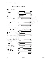
Page 32: ...Piranha Color Camera User s Manual 32 DALSA 03 032 10211 01 5 9 2007 Exposure Modes in Detail ...
Page 72: ...Piranha Color Camera User s Manual 72 DALSA 03 032 10211 01 5 9 2007 ...
Page 88: ...Piranha Color Camera User s Manual 88 DALSA 03 032 10211 01 5 9 2007 ...
Page 90: ...Piranha Color Camera User s Manual 90 DALSA 03 032 10211 01 5 9 2007 ...
Page 92: ...Piranha Color Camera User s Manual 92 DALSA 03 032 10211 01 5 9 2007 ...
Page 94: ...Piranha Color Camera User s Manual 94 DALSA 03 032 10211 01 5 9 2007 ...


