96
•
Appendix A: Camera Link
Figure 36: SDR-26 Mini Camera Link Connector
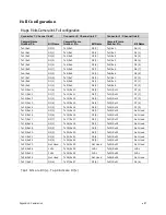
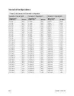
Data 2
Control / Data 1
Camera
Connector
Right Angle
Frame Grabber
Connector
Channel Link
Signal
Camera
Connector
Right Angle
Frame Grabber
Connector
Channel Link
Signal
1
1
inner shield
1
1
inner shield
14
14
inner shield
14
14
inner shield
2
25
Y0-
2
25
X0-
15
12
Y0+
15
12
X0+
3
24
Y1-
3
24
X1-
16
11
Y1+
16
11
X1+
4
23
Y2-
4
23
X2-
17
10
Y2+
17
10
X2+
5
22
Yclk-
5
22
Xclk-
18
9
Yclk+
18
9
Xclk+
6
21
Y3-
6
21
X3-
19
8
Y3+
19
8
X3+
7
20
100 ohm
7
20
SerTC+
20
7
terminated
20
7
SerTC-
8
19
Z0-
8
19
SerTFG-
21
6
Z0+
21
6
9
18
Z1-
9
18
CC1-
22
5
Z1+
22
5
CC1+
10
17
Z2-
10
17
CC2+
23
4
Z2+
23
4
CC2-
11
16
Zclk-
11
16
CC3-
24
3
Zclk+
24
3
CC3+
12
15
Z3-
12
15
CC4+
25
2
Z3+
25
2
CC4-
13
13
inner shield
13
13
inner shield
26
26
inner shield
26
26
inner shield
*Exterior Overshield is connected to the shells of the connectors on both ends. Unused pairs
should be terminated in 100 ohms at both ends of the cable. Inner shield is connected to
signal ground inside camera

