background image

SMAVIA Appliance

www.dallmeier.com

28

9.2 

Deactivation

The failure of a power supply module will be displayed cyclically by a system message (lo-

cal and alarm host) until the exchange. This feature can be disabled to avoid unnecessary 

repeated messages.


Open the 

Service Settings

 dialog via 

System

 > 

Service

 > 

Settings

.

Fig. 9-4 

Checkbox 

Check power supply

 disabled  =  Power supply switched on and OK

Checkbox 

Check power supply

 enabled  =  Power supply switched off or defective


Deactivate the defective power supply module if required.


Confirm with 

OK

.

The display of the corresponding system message is suppressed. After replacing the pow-

er supply module this function is activated automatically, a resetting is not required.

9.3 

Exchange

If the device is powered by two redundant power supply modules, one can be exchanged 

during operation.


Turn off the defective power supply module with the appropriate power switch.


Remove the power cable.

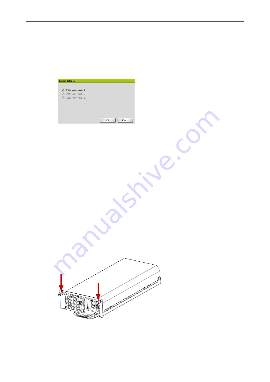
Fig. 9-5 


Loose the screws at the top of the power supply module.

Summary of Contents for IPS 2400

Page 1: ...Service English Rev 1 1 0 2014 10 06 Appliance PRELOADED IPS2400...

Page 2: ...ct or documentation e g print or spelling errors and for those not caused by intention or gross negligence of the manufacturer Dallmeier electronic GmbH Co KG Cranachweg 1 93051 Regensburg Germany www...

Page 3: ...ses 13 6 Update 14 6 1 Maintenance License 14 6 2 Implementation 15 7 System Parameters 16 7 1 Default Parameters 16 7 2 Export Parameters 16 7 3 Import Parameters 17 8 HDDs 19 8 1 Identify 19 8 1 1 I...

Page 4: ...rained system integrators Commissioning Instructions for installation connection and commissioning for trained system integrators Service this document Instructions for maintenance and cleaning for tr...

Page 5: ...lt in minor or moderate injury NOTICE NOTICE indicates practices for preventing property damage incorrect configurations or faulty operations For reasons of clarity and readability various text format...

Page 6: ...may result in the loss of warranty Modifications Do not make any modifications to the hardware or software that have not been tested and approved by Dallmeier Inappropriate modifications may cause ma...

Page 7: ...cause malfunctions and damages The units may not be moved while in operation Foreign Bodies If objects or liquids get into the units immediately disconnect them from the power supply pull out the powe...

Page 8: ...megapixel video channels High storage capacity due to integrated storage system High recording speed due to concerted components Easy Change functionality for hard disk drives hot swap Components opti...

Page 9: ...umentation Commissioning It contains detailed instructions on mounting connection assignment and commissioning of the device 4 1 Local Login In order to access the configuration interface of the appli...

Page 10: ...SMAVIA Appliance www dallmeier com 10 The configuration interface is displayed Fig 4 2 Make the required settings see below Click Close in order to exit the configuration interface...

Page 11: ...a tion Note the documentation Operation of the PService application Start PService Scan the network Select the required appliance Open the context menu with a right click Click NetConfig3 The connecti...

Page 12: ...SMAVIA Appliance www dallmeier com 12 The configuration interface is displayed Fig 4 4 Make the required settings see below Click Close in order to exit the configuration interface...

Page 13: ...se of a hardware extension in conjunction with a licen se code Open the License Code dialog via System Service Extensions Fig 5 1 Enter the license code Click OK in order to save the entry After the a...

Page 14: ...mplete licensing of the appliance An appliance is to be updated in the third year of operation with a newly released update In this case maintenance licenses for the year one free license and for the...

Page 15: ...ppliance can be triggered by an unstable power supply or via the contact IN interface Open the Software Update dialog via System Service Software Update Fig 6 2 Select the storage medium as Source Dow...

Page 16: ...recording settings will be lost Open the System Parameters dialog via System System Parameters Default Fig 7 1 Click OK The default system parameters will be restored 7 2 Export Parameters The system...

Page 17: ...port Parameters Secured or modified system parameters can be imported to restore the configuration of the SMAVIA Recording Server NOTICE Data loss System failure Inappropriate or incorrectly modified...

Page 18: ...Note the detailed explanations in the dialog Click Search USB stick if required Select the required storage medium as a Source Select the relevant import option Finally click OK in order to start the...

Page 19: ...tive hard disk drive must be identified There are two options available for this purpose via the infor mation dialog or via the display on the front side of the appliance 8 1 1 Information Dialog In t...

Page 20: ...AID sys tem 8 2 1 With RAID System The integrated RAID technology allows continuous recording when a hard disk drive fails The defective hard disk drive can be replaced during operation hot swap Proce...

Page 21: ...disk drive is recovered and the recording is continued on the remaining hard disk drives Identify the defective hard disk drive XXX Fig 8 3 Replace the defective hard disk drive see below The new hard...

Page 22: ...s must be tested and released for the installation by Dallmeier HDD white list on www dallmeier com new HDDs should not be formatted and not be partitioned Recommended Procedure For The Case Of Servic...

Page 23: ...oning of the hard disks drives are automa tically performed The recording continues after the final reboot No further settings have to be made 8 3 Exchange In order to exchange a defective hard disk d...

Page 24: ...t CAUTION Risk of injury from sharp edges Use care when installing the HDD drawer unit Fig 8 9 Remove the 4 screws Remove the defective hard disk drive Place the new hard disk drive in the HDD drawer...

Page 25: ...e rail Fig 8 11 Slide the HDD drawer unit carefully and completely into the housing Make sure not to cant Do not use any force Fig 8 12 Make sure the HDD drawer unit and the housing are flush Lock the...

Page 26: ...modules 9 1 Identify In the case of service the faulty power supply module must be identified first This includes three available options via the information dialog via the display on the front side...

Page 27: ...it is defective switched off The fan of the power supply unit is defective Power supply unit is not mounted Check the status of the power supply modules in the display Identify the failed power supply...

Page 28: ...kbox Check power supply enabled Power supply switched off or defective Deactivate the defective power supply module if required Confirm with OK The display of the corresponding system message is suppr...

Page 29: ...shock Do not grip to the open shaft of the power supply module Insert no tools in the open shaft of the power supply module Fig 9 7 Place the new power supply module with the guide rails in the housi...

Page 30: ...SMAVIA Appliance www dallmeier com 30 The power supply module is put into operation automatically The device is powered from the redundant power supply modules with equal parts of tension...

Page 31: ...specialists If a cleaning of the appliance is required observe the following guidelines NOTICE Damage to the surface of the device Do not use cleaning materials that contain solvents because they can...

Reviews: