background image


DGM02


Device Manual


Made in Italy 


DALCNET S.r.l.  

36077 Altavilla Vicentina (VI) 

 Italy 

Via Lago di Garda, 22


Tel. +39 0444 1836680 

www.dalcnet.com 


[email protected]


Rev. 

06/12/2022 - 

Pag. 

8/32 


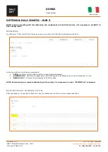
HOME PAGE 


D

EVICE INFO


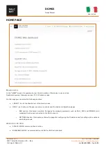
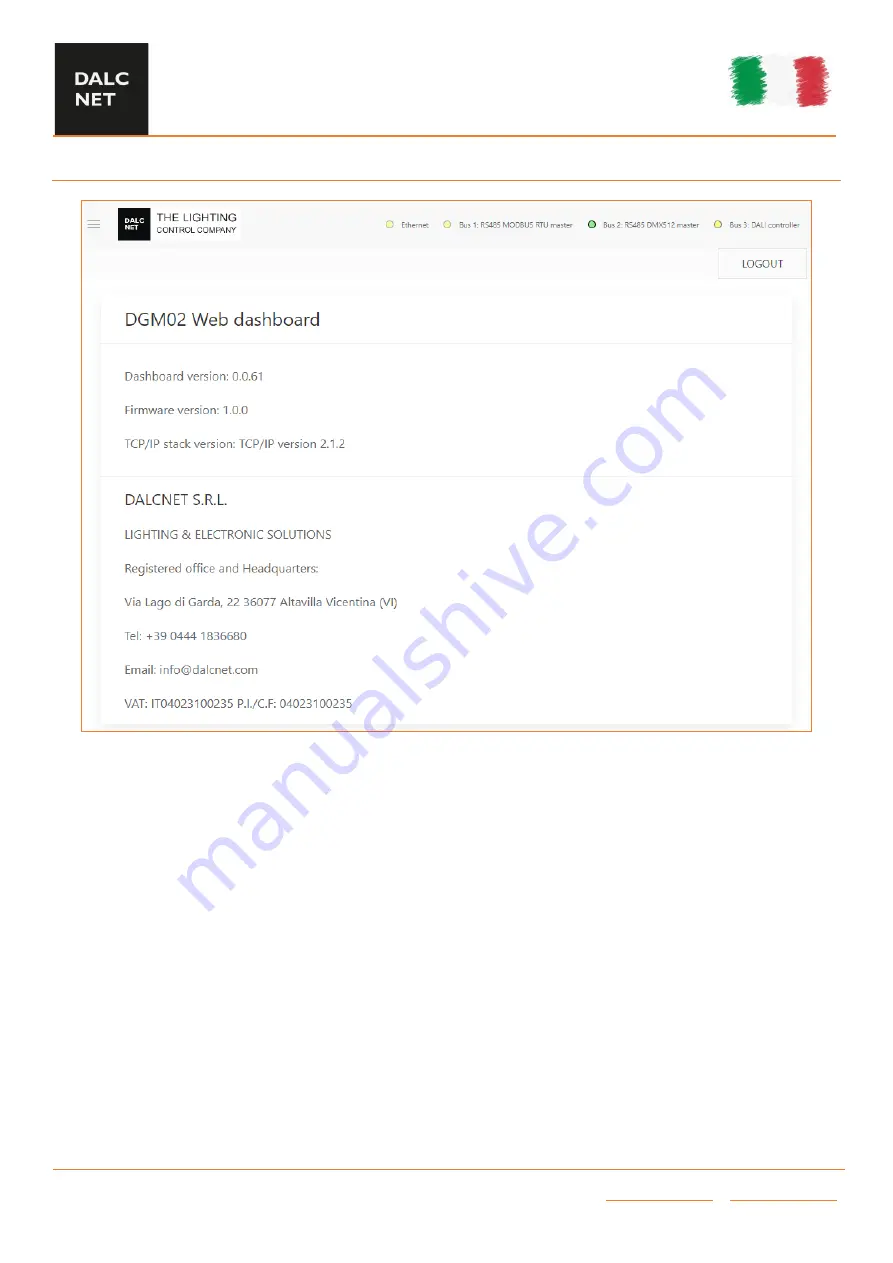
In the “HOME” screen it is possible to view the information of the device in use such as: 


Dashboard version, Firmware version, TCP / IP stack version. 
 
On this page you can select the following sections: 


LOGOUT, to exit the Web Server of the device in use. 


MENU ', by clicking on the pop-up menu you can access the device configuration pages. 


o


BUS  section:  this  section  contains  the  pages  for  managing  protocols,  such  as  DALI,  DMX  and  MODBUS,  and 
managing the devices connected to the DALI network; 


o


SETTINGS Section: this section contains the pages for configuring the IP address and for setting up the network 
and BUS protocols. 


WEB SIDE LED INFO


STEADY GREEN: communication is active 


BLINKING YELLOW: no communication via BUS or BUS not activated 


Summary of Contents for DGM02

Page 1: ...Vdc Input current 550mA max Nominal Power1 typ max 12V 160 mA 1 92W 550 mA 6 60W 24V 80 mA 1 92W 260 mA 6 24W 48V 50 mA 2 40W 150 mA 7 20W PoE1 min2 typ max 46 5V 40 mA 1 9W 100 mA 4 65W 170 mA 7 9W...

Page 2: ...addressable lighting interface Part 103 General requirements Control devices IEC 62386 205 ED 23 Digital addressable lighting interface Part 205 Particular requirements for control gear Supply voltage...

Page 3: ...XLR connector PINOUT CONNECTORS PIN RJ45 A RJ45 B crossed RJ45 B RJ45 A crossed 1 White Green White Orange 2 Green Orange 3 White Orange White Green 4 Blue Blue 5 White Blue White Blue 6 Orange Green...

Page 4: ...o communication only RTU BUS2 not enabled LED4 First from right BUS DALI Connected with communication Connected with no communication DALI BUS not enabled BUS power off RESET BUTTON Device Restart Pre...

Page 5: ...tion and the power must be dimensioned correctly In the case of power supplies equipped with ground terminals it is mandatory to connect ALL protective ground points PE Protection Earth to a properly...

Page 6: ...ng a group 16 State of the dali node 16 DALI CONTROLLER BUS 3 17 DMX512 GLOBAL SETTINGS RS485 DMX MASTER BUS 1 BUS 2 18 DMX512 GLOBAL SETTINGS RS485 DMX SLAVE BUS 1 BUS 2 19 MODBUS MASTER RS485 MODBUS...

Page 7: ...re transmitted entirely on the DMX512A bus On the DALI bus the first 64 channels of the buffer are transmitted as 64 short addresses or the first 16 channels as 16 group addresses or 1 channel as broa...

Page 8: ...n select the following sections LOGOUT to exit the Web Server of the device in use MENU by clicking on the pop up menu you can access the device configuration pages o BUS section this section contains...

Page 9: ...sible if in DALI CONFIG mode or RS485 Bus not enabled RS485 on this page you can configure the settings for the sending speed of the RS485 packet not visible if in DALI CONFIG mode or RS485 Bus not en...

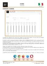
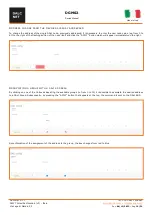
Page 10: ...available channels by clicking on the GO TO FIRST GO TO LAST buttons or by advancing one or eight channels at a time by clicking on the 1 or 8 icons The same is true if you want to go back one or eigh...

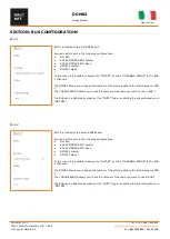
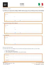
Page 11: ...first channel of BUS 1 The CHANGE RANGE allows you to set the number of channels you want to use in BUS 1 The BUS can be disabled by means of the MUTE flag or by setting the bus configuration in NOT...

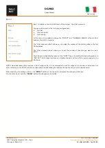
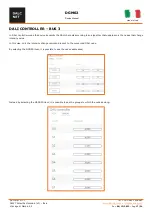
Page 12: ...starting slide to the first DALI address The DALI channels range allows you to set the number of channels you want to use in BUS 3 The BUS can be disabled by means of the MUTE flag or by setting the...

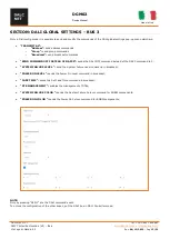
Page 13: ...ast commands SEND COMMAND OFF INSTEAD OF DAPC0 sends the DALI OFF command instead of the DAPC command to 0 SYSTEM FAILURE LEVEL send the System Failure Level command in broadcast POWER ON LEVEL sends...

Page 14: ...onfig from the pop up menu we enter the DALI device addressing interface At the top right are the following commands SCAN performs the acquisition of DALI nodes already addressed ADDRESS ALL performs...

Page 15: ...ode value eg from 0 to 63 to the right of the flashing button of the node itself and click the APPLY button which will appear immediately on the right ASSOCIATING A GROUP WITH A DALI ADDRESS By clicki...

Page 16: ...s possible to remove the desired address from a DALI Group Subsequently by pressing the APPLY button that appears at the top the command is sent on the DALI BUS Removal from the G3 group of the A0 add...

Page 17: ...BUS 3 In DALI Controller mode the device transmits the DALI channels according to an algorithm that updates only the nodes that change intensity value In this way only the intensity change command is...

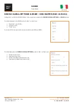
Page 18: ...MX512 Master in the pop up menu activates the DMX512 GLOBAL SETTINGS and RS485 sections The fields displayed in the RS485 section for Bus 1 or Bus 2 are Baud rate only 250000 Stop bit 2 bits Parity no...

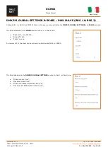
Page 19: ...X512 Slave in the pop up menu activates the DMX512 GLOBAL SETTINGS and RS485 sections The fields displayed in the RS485 section for Bus 1 or Bus 2 are Baud rate only 250000 Stop bit 2 bit Parity no on...

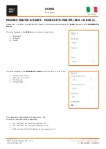
Page 20: ...sections and the MODBUS RTU Master The fields displayed in the RS485 section for Bus 1 or Bus 2 are Baud rate Stop bit Parity The fields displayed in the MODBUS RTU Master section for Bus 1 or Bus 2 a...

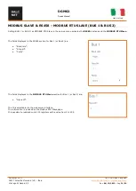
Page 21: ...2 as MODBUS RTU Slave in the pop up menu activates the RS485 sections and the MODBUS RTU Slave The fields displayed in the RS485 section for Bus 1 or Bus 2 are Baud rate Stop bit Parity The fields dis...

Page 22: ...rded in the LOG section In this case it is useful to configure the type of diagnostics by accessing the Log Configuration section the following page will be displayed The SECURITY LEVEL sets what type...

Page 23: ...the Network section you can change the IP Address the Netmask The MAC Address is unique to the product and cannot be changed After modifying the settings click on the APPLY button at the top right ot...

Page 24: ...d USER In ADMIN mode you have full access to the system settings and the default credentials are Username admin Password admin In USER mode it is possible to view only the Channels section and the def...

Page 25: ...ded correctly within the DGM02 4 Once the upload is complete click on the Reboot button 5 After having pressed the Reboot button the DGM02 will reboot 6 At the next switching on the 2 leftmost LEDs wi...

Page 26: ...ev 06 12 2022 Pag 26 32 SACN ETHERNET DGM02 implements the sACN protocol and can be used as a sACN DMX and sACN DALI gateway from the main software and lighting control systems The port used is UDP 55...

Page 27: ...t in a single ASCII string DATA LEVEL The request is enclosed by the data and data tags data addr 0000 size 0200 data The addr field indicates in hexadecimal notation the first slot to be transmitted...

Page 28: ...MODBUS configured as master 0x91 MODBUS configured as slave 0xBF Multiple bus definition 0xFF DALI node not defined type 010800 type t1 t2 t3 SET RGBWAF DALI DT8 COLOUR LEVELS This command is used to...

Page 29: ...ess refers to the current position on the DB where the Dali node is located Size maximum size 64 Set color levels DT8 TW devices only sctc addr 0000 size 0001 FD01 sctc To calculate the command value...

Page 30: ...e slope is limited internally The value 0000 indicates to stop fading at the actual value The addr field indicates in hexadecimal notation the first slot to be transmitted The size of the field indica...

Page 31: ...ts the Art Net 4 protocol and can be used as an Art Net DMX and Art Net DALI gateway from the main software and lighting control systems The port used is UDP 6454 IMPLEMENTED PACKET OpCode Note ArtDmx...

Page 32: ...12A universe to one or more Modbus devices on the Ethernet network 512 registers are available with Modbus address from 0 to 511 and value from 0 to 255 The port used is TCP 502 the Slave ID is not co...

Reviews: