VIP-5000 Series Quick Guide
DD2773153
Rev 06
30 January 2018
Page 4 of 6
201 Daktronics Drive
Brookings, SD 57006-5128
www.daktronics.com/support
800.325.8766
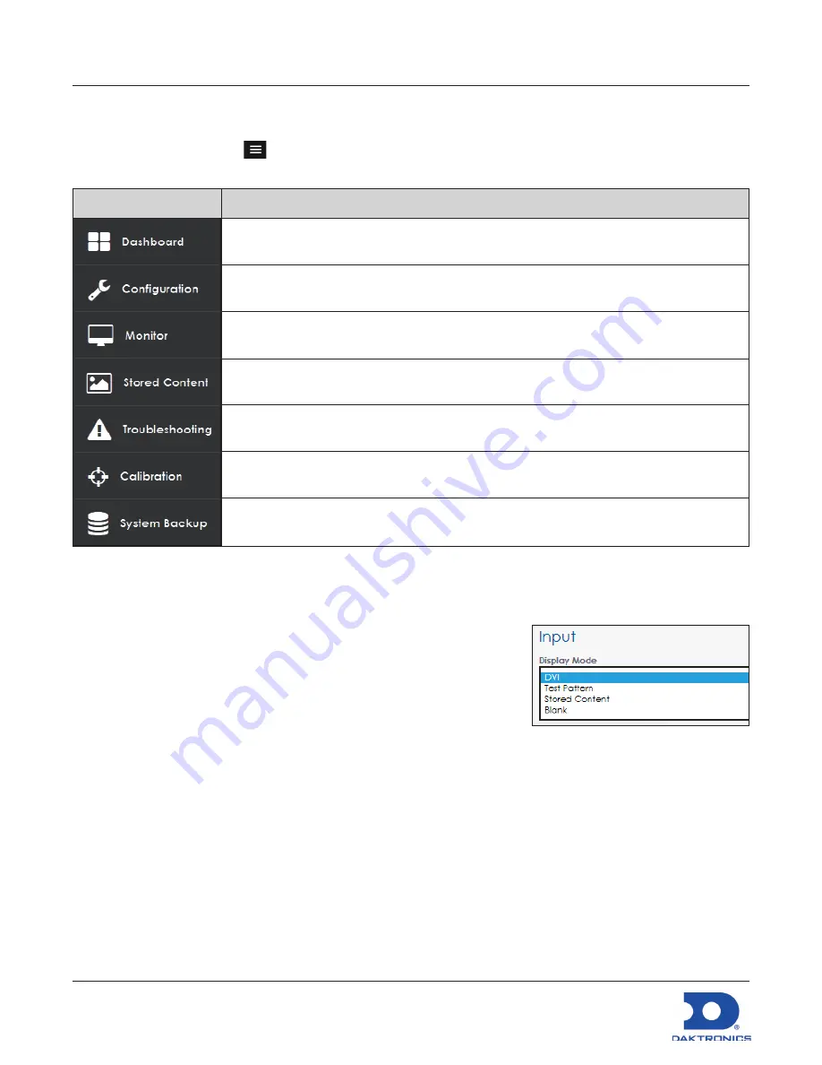
Processor Menu Overview
After initial login, the
Dashboard
window opens showing status tiles for various aspects of the device.
Click the
Show Menu
icon
in the upper-left corner to expand the main menu. Refer to the table
below. For more information, refer to the
VIP-5000 Series Operation Manual (DD2773153)
.
Menu Item
Description
Shows status tiles for various aspects of the processor; most tiles trigger operational
windows but some tiles only provide information
Lists all available configuration settings and tools including setting the input, output,
brightness levels, local time, and location
Opens a window showing a video feed of the display content
Shows existing stored content files and allows images to be added or removed
Lists troubleshooting options including testing, resetting power, and resetting the
processor
Lists calibration tools used to adjust individual modules to blend with surrounding
modules
Lists system backup options including creating a system backup and restoring a system
backup
System Configuration
Configuring Input
Select the processor’s type of input including selecting a DVI video
source, choosing a built-in test pattern, loading static images, or
blanking the display. Refer to
Figure 15
. To configure the processor
for a DVI video source, follow the steps below:
1.
Select
Configuration
from the main menu or click the
Input
tile on
the dashboard.
2.
Click
Input
.
3.
Choose
DVI
from the
Display Mode
drop-down list.
4.
Change the
Color Adjustment
settings of the DVI video signal with the
Brightness
,
Contrast
,
Saturation
, and
Hue
slider bars if desired.
5.
Set the
Source Dimensions
as either
Automatic
or
Manual
to define what portion of the incoming
video signal is shown on the display. This setting is normally determined at the factory.
• Automatic
- the controller positions the content and the dimensions will match the configured
display size.
• Manual
- the operator manually defines the visible area.
Figure 15:
Input Display Mode


