


VIP 4500 Configuration Using Venus
®
7000 Software
9
Section 3:
VIP 4500 Configuration Using Venus
®
7000 Software
The V7 VLink Controller in the Venus
®
7000 software program allows the operator to control
multiple VIP
4500s. Each processor can output up to four video sources simultaneously. This section
focuses on setting up, adjusting, and operating multiple processors and their inputs using the Venus
®
7000 software
.
DMP-7000 Installation and Setup Manual
) for
more information.
1.
In the Venus 7000 Shell, open the V7 VLink Controller application by clicking the
V-Link
4500
icon or by pressing
[V]
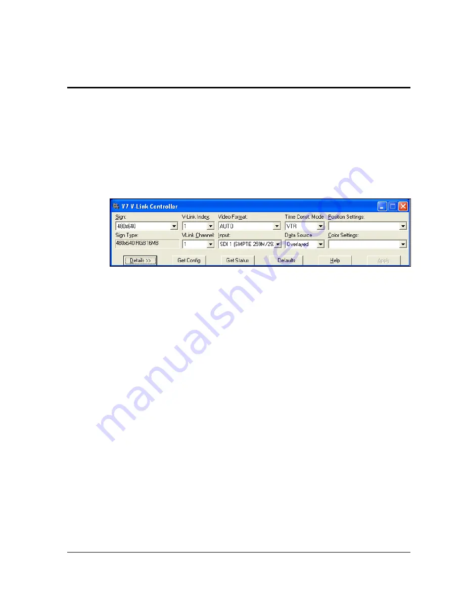
. The V7 VLink Controller dialog box opens; refer
to
2.
If the sign to configure does not display in the Sign drop-down box, click the
drop-down
arrow
next to Sign and select the sign to control. Users may also highlight the
Sign drop-
down box
and use the
[up]
and
[down arrows]
to select the sign. After selecting a sign,
the Sign Type automatically populates.
3.
To select which VIP 4500 to control, click the
drop-down arrow
next to VLink Index and
select the processor or press
[Alt]
+ [X
]
and use the
[up]
and
[down arrows]
to select it.
Up to three processors may connect to the Venus
7000 controller per sign.
4.
To select which channel to control, click the
drop-down arrow
next to VLink Channel and
select the channel or press
[Alt] + [C]
and use the
[up]
and
[down arrows]
to select it. Up
to four channels can display per VIP 4500.
5.
Set the video format for each channel. Click the
drop-down arrow
next to Video Format
and select the preferred format. Users may also press
[Alt] + [
M
]
to move the cursor to
the Video Format box and use the
[up]
and
[down arrows]
to select the video format.
Note:
Auto works well as a format for most applications.
Figure 6: V7 V-Link Controller Dialog Box