


12
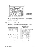
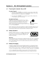
RC-100 Base Station
#
LED
Color
Function
1
POWER
Green
This LED illuminates when the Base Station or receiver is
connected to a power source.
2
CL/RS232 TX
Red
This LED flashes when the Base Station transmits Current
Loop (CL) or RS-232 data via wire:
Current Loop output is used to control a connected
display.
RS-232 output is used to communicate with external
devices.
3
CL/RS232 RX
Green
This LED flashes when the Base Station receives Current
Loop (CL) or RS-232 data from another device via wire.
4
IN RANGE
Amber
On a server Base Station, this LED flashes several times at
start-up to indicate that it is searching for other server Base
Stations on the same channel within range. If one is found,
this LED flashes continuously to indicate that only one
server Base Station is allowed on a given channel. Once in
operation mode, this LED will either be on or off to indicate
whether or not one or more handheld devices are currently
connected to the Base Station.
On a client Base Station, this LED is on whenever it is
connected to a server Base Station.
This LED also shows sync status. Refer to the
Section 3.3
.
5
CAN TX
Green
This LED flashes when Controller Area Network (CAN) data
is transmitted to a connected device.
6
CAN RX
Red
This LED flashes when Controller Area Network (CAN) data
is received from a connected device.
LED Error Diagnostics
The CL/RS232 TX, CL/RS232 RX, IN RANGE, and CAN TX LEDs are also used to display
errors that can occur in wireless Base Station operation. Refer to Section 9 for more
information about these errors.


