Electrical Installation
8
9�
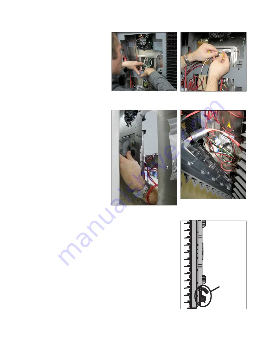
Locate the wiring inside of the junction box and pull all three wires out of the box, as
shown in
10�
Remove the
1
/
2
″
conduit rubber plug
or plugs on the rear
the junction box, or
the flexible
1
/
2
″ conduit
routed from the
electrical source can
be connected. Refer
.
11�
Use wire nuts or other
appropriate hardware
to connect the wires
coming through the
conduit to the wires in
the junction box. Refer
.
12�
Push all wires back into
the junction box and
reattach the gasket
and cover with
3
/
16
″ nut
driver.
13�
Reconnect SATA
and power cables to
the module. Refer to
.
14�
Place modules back
into their proper
locations by inserting
the tabs at the bottom
of the modules in the
corresponding slots on
the display face sheet. Refer to
. Tip the top
of the module back into place and latch it by turning
the hex head wrench a quarter-turn clockwise.
Grounding
Galaxy
®
eCCB series displays do not require a local earth-
ground electrode.
The displays are designed so the most sensitive
components are isolated and an earth ground is not
required and is no longer recommended.
The displays still require a safety ground from the electrical
service panel for the primary power wires to comply with
national electric codes.
Please note that earth-grounding requirements for other
Daktronics products remain unchanged.
Figure 10:
Pull Wires into Term
Panel
Figure 11:
Connect Wires with
Wire Nuts
Figure 12:
Attach Conduit Fitting
Figure 13:
Reinstall Modules
Module
Tab
Figure 14:
Tab on Back of
Module


