Maintenance and Troubleshooting
42
9 Maintenance and Troubleshooting
Important Notes:
• Visit Daktronics Support videos at
www.youtube.com/daktronicssupport
.
• Disconnect power before any repair or maintenance work is done on the display.
•
Qualified service personnel must make any access to internal display electronics.
• Disconnect power when the display is not in use. Leaving power on for prolonged
periods of time shortens the life of some electronic components.
Visual Structural Inspection
At least once a year:
• Check the display to ensure the structure and
components are in good condition.
• Inspect the paint and cabinet for corrosion.
• Make sure fasteners are tight; tighten or
replace as required.
Display Diagnostics
Driver Diagnostic LEDs
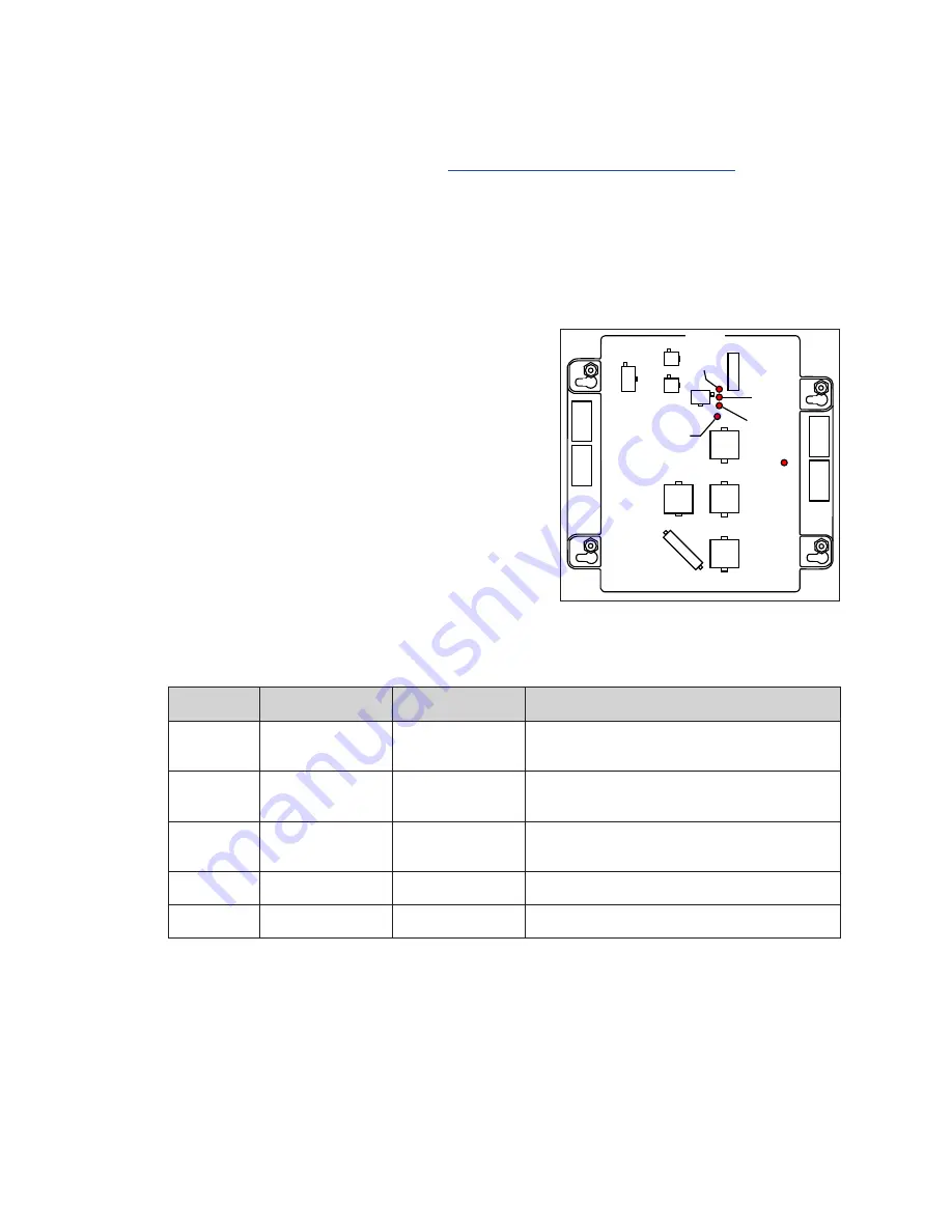
The driver has five LEDs that indicate whether it is
functioning properly. Refer to
locations. These LEDs can help pinpoint problems
with driver setup or operation.
The following table provides a key to what the diagnostic LEDs indicate:
LED Name Function
Label
Indication
DS1
Status
Comm Port Status Blinks when communication is detected.
Off when no communication is detected.
DS2
Status – J10 Status Line to Line
On when connected.
Off when disconnected.
DS3
Status – J9 Status
Line to Line
On when connected.
Off when disconnected.
DS4
Driver Status
Heartbeat
Blinks once per second when OK.
DS7
Power
Power
On when receiving power.
POWER IN
24 DC
J14
DIGIT 4
J13
DIGIT 3
J12
DIGIT 2
J15
DECIMAL
J11
DIGIT 1
J18
J10
J9
J16
DS7
POWER
ON = GOOD
DS4 HEARTBEAT
1 SEC. BLINK = OK
DS3 (J9)*
DS2 (J10)*
LINE TO
LINE
DS1 (J16)
COMM
PORT
STATUS
LINE
TO
LINE
CASH/
CREDIT
COMM
PORT
J3
Figure 66:
Driver Diagnostic LED Locations


