Quick Guide: Digit Display Installation with FLR 1500 Control Kit
3 of 5
2.
Plug the other end of this cable into the Input jack (J13) on
the next display driver. Continue with this pattern, going
from the output of one driver to the input of the driver in
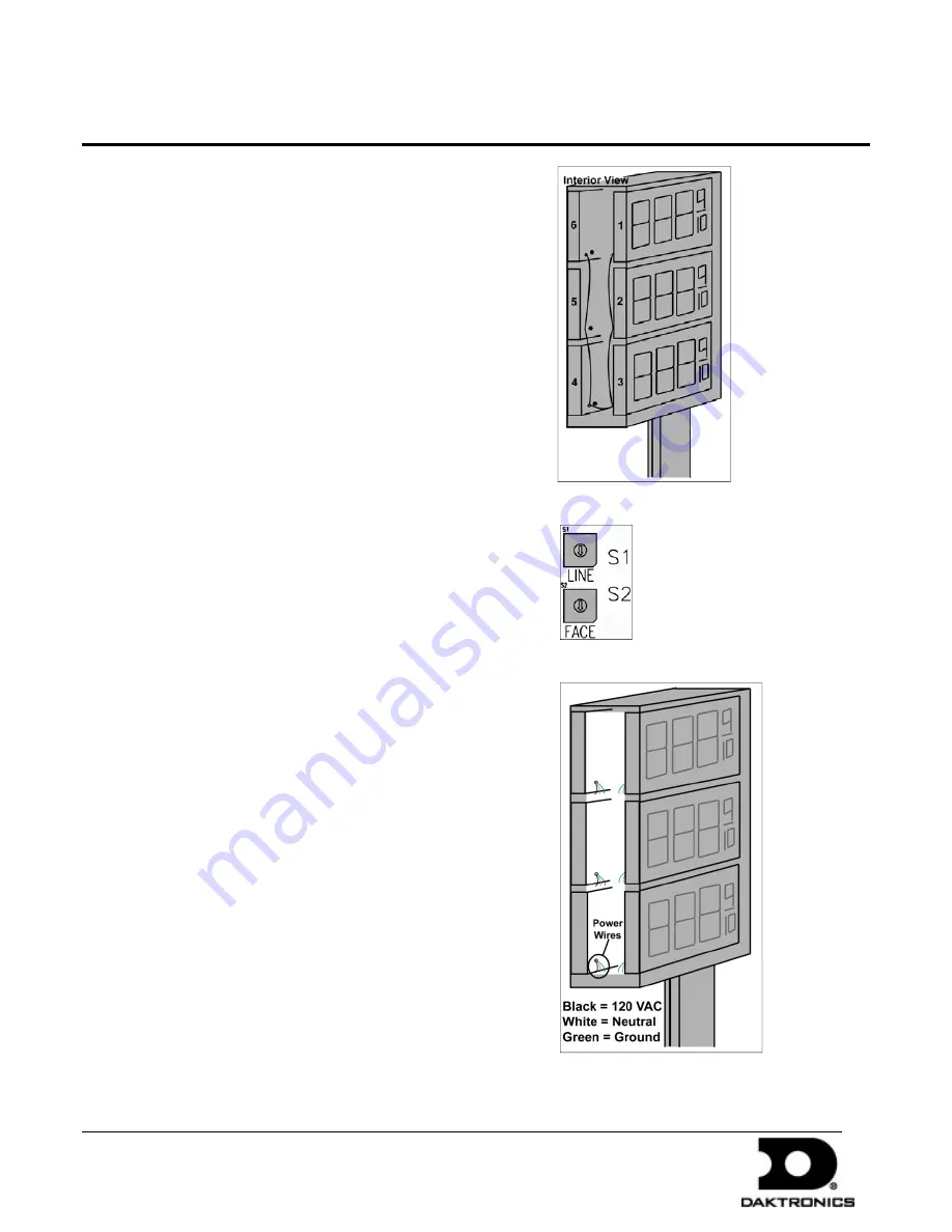
the next display. Refer to
Figure 5
and
Figure 6
for signal
routing overviews.
Figure 6: Signal Routing
Figure 7: Rotary Switches
Figure 8: Power Installation
Note
: Three displays are shown per face, but the hand-held
controller can control up to five displays per face.
3.
After plugging in the RJ cable(s) on a driver, set the display
line and face numbers using the rotary switches. Refer to
Figure 7
.
4.
Each installation consists of a number of faces with multiple
displays installed in each face. The line and face number for
each display is set using the rotary switches. Refer to
Figure
7
. Displays with the same line number will display the same
price.
Power Installation
1.
Open each display and locate the power harness (pigtail)
inside.
2.
Open one of the knockouts to be used for power connection.
Place a fitting in the knockout opening to cover sharp edges.
3.
Route the end of the power harness out the knockout, as
shown in
Figure 8
.
4.
Connect the wires from each display to the main power
cable according to local and national electrical codes.
5.
Each display system must be connected to an earth-ground
electrode with a resistance to ground of 10 ohms or less.
6.
Terminate power to a dedicated 120 VAC circuit. Consult
the display specifications in the display manual to ensure
that this circuit is adequate for the specific displays.
Note
: This circuit must not be linked to the building’s energy
management system.
7.
Turn power on and watch for boot-up sequence. After boot-
up, each display should show “E4,” noting that the display
has power but no message is currently stored on the driver.
PO Box 5128 201 Daktronics Dr Brookings SD 57006-5128
tel 605-697-4036 or 800-325-8766 fax 605-697-4700
www.daktronics.com
DD1399086 Rev 2
12 April 2010


