Maintenance & Troubleshooting
27
Replacing a Driver
If the driver status indicators do not appear to be working correctly, it may be necessary to
replace the driver.
1.
Open the digit panel or scoreboard face panel as described in
Section
2.
Disconnect all connectors from the driver
by squeezing together the locking tabs and
pulling the connectors free.
Note:
It may be helpful to label the cables to know which cable goes to which
connector when reattaching the driver.
3.
Remove the wing nuts securing the driver to the driver tray.
4.
Carefully lift the driver from the display and place it on a clean, flat surface.
5.
Position a new driver over the screws and tighten the nuts.
6.
Reconnect all power/signal connectors.
Note:
The connectors are keyed and will attach in one way only. Do not attempt to
force the connections.
7.
Ensure the driver is set to the correct address (refer to
Setting the Driver Address
).
8.
Close and secure the access panel, then power up and test the scoreboard to see if
changing the driver has resolved the problem.
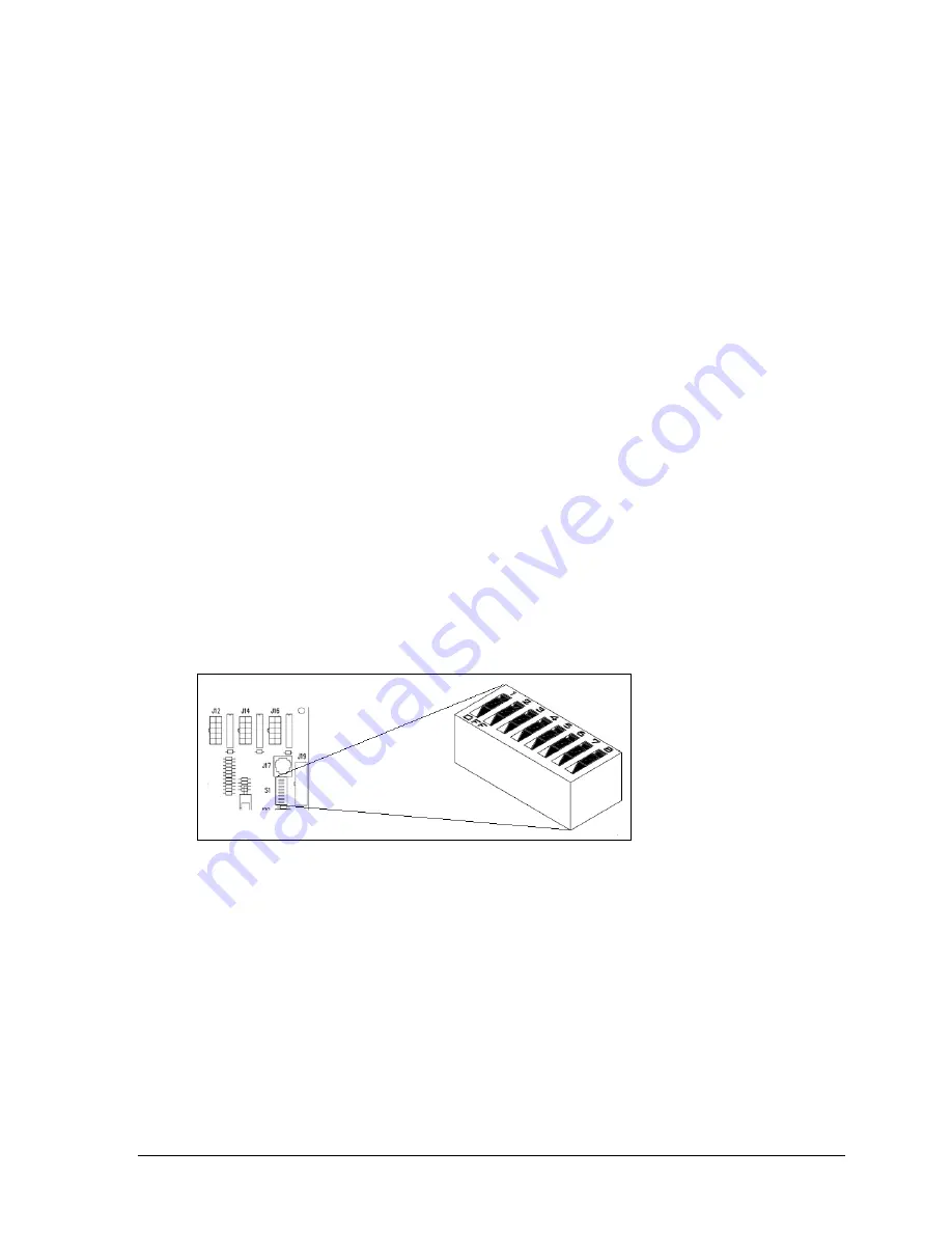
Setting the Driver Address
Since the same LED drivers can be used for many scoreboard models, each driver must be set
to receive the correct signal input, or address, for the model being used. Addresses are set
through the S1 DIP switch on the driver (
) using a pen or small, pointed object.
When setting the driver address, first refer to the specifications table in
Section 2
to find the
correct driver address(es) for a particular scoreboard model. Then refer to
Drawing A-284772
in Appendix E
for addressing information for driver addresses 1 – 128.
Multiple Drivers
Scoreboards that require multiple drivers operate using a master/slave driver configuration.
Master and slave drivers function identically, but slave units lack the power/signal
termination blocks. The two drivers have been designed to simply plug into one another, and
this is done at the factory, so no additional on-site connection is necessary.
If it appears as though only a certain group of digits on the scoreboard is not functioning,
there may be a problem with the slave driver(s) or the power/signal connection from the
other driver(s).
Figure 13:
Driver Address DIP Switch (ColorSmart Driver)
Summary of Contents for COLORSMART BB-3102
Page 2: ......
Page 4: ......
Page 10: ......
Page 26: ......
Page 38: ......
Page 46: ......
Page 48: ......
Page 50: ...PERIOD B B daktronics DAKTRONICS GUEST HOME ...
Page 51: ......
Page 52: ......
Page 53: ......
Page 54: ......
Page 55: ......
Page 56: ...B PTS FOULS PLYR HOME PERIOD FOUL B daktronics FOULS GUEST ...
Page 58: ......
Page 59: ...GUEST B HOME PERIOD B PERIOD B HOME B GUEST B B ...
Page 61: ...GUEST GUEST B HOME PERIOD B PERIOD B HOME B B B B B ...
Page 66: ......
Page 67: ......
Page 69: ......
Page 70: ......
Page 71: ......
Page 72: ......
Page 73: ...5 TAN RED 1 3 SIGNAL VIO BLK 2 PNK 4 ...
Page 74: ......
Page 76: ......
Page 77: ......
Page 78: ......
Page 79: ......
Page 80: ...04 01 OCT 12 KZB ADDED RADIO HARNESS DETAILS ...
Page 82: ......
Page 83: ......
Page 84: ......
Page 85: ......
Page 86: ......
Page 87: ......
Page 88: ......
Page 89: ......
Page 90: ......
Page 91: ......
Page 92: ......
Page 93: ......
Page 94: ......
Page 95: ......
Page 96: ......
Page 97: ......
Page 98: ......
Page 100: ......
Page 104: ......
Page 106: ......


