background image

Troubleshooting guide. 
 

Problem   Possible 

cause 

  Solution 

 
Gauge will not light up   

Red wire does not have  

Connect to a location that has power 


  power.  


  when the key is on. 


Black wire is not getting  

Connect ground to a different location. 


good 

ground. 


Fuse is blown.   


Replace in line fuse.  (2 amp only.) 


Gauge is damaged. 


Return gauge for repair.  (see instructions) 

Gauge lights up, but does 

Loose connection on red 

Reconnect red wire. 

  not read correctly. 


  power wire. 


Poor ground connection. 

Move ground to different location 

Sensor not connected   

Make sure that the 6-pin connector is plugged 

  properly. 


  in to the sensor. 

    Sensor 

cable 

is 

cut 

or 

 Return sensor for repair.  (see instructions) 


damaged 


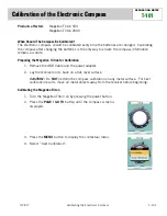
Calibration is not correct. 

Repeat calibration procedure. 

    Sensor 

is 

damaged. 

 Return 

sensor for repair.  (see instructions) 


Gauge is damaged. 


Return gauge for repair.  (see instructions) 

Display will only read 


Sensor is not connected. 

Connect the sensor to the gauge. 

  “000  -N-” 


Sensor is not connected  

Check the connector to make sure it is 


properly. 

  aligned 

properly 

and 

tight. 


Poor ground connection. 

Move ground to different location 

    Signal 

wire 

is 

grounded 

or 

Inspect 

sensor cable for cuts or abrasions. 


broken. 

    Sensor 

is 

damaged. 

 Return 

sensor for repair.  (see instructions) 


Gauge is damaged. 


Return gauge for repair.  (see instructions) 

Gauge will not dim. 


Blue wire is not connected 

Check wiring connections. 


  correctly. 

Gauge remains dim at all 

Blue wire is getting power 

Connect blue wire to location that only 

  times.   


  all of the time.   


  has power when the headlights are on. 

    Battery 

is 

very 

low. 

 Recharge or replace vehicle battery. 


Gauge is damaged. 


Return gauge for repair.  (contact factory) 


SERVICE AND REPAIR 

DAKOTA DIGITAL offers complete service and repair of its product line.  In addition, 

technical consultation is available to help you work through any questions or problems you 
may be having installing one of our units. 

Should you ever need to send the unit back for repairs, please package the product in a 

good quality box along with plenty of packing material.  Ship the product by UPS or insured 
Parcel Post.  Be sure to include a complete description of the problem, your full name and 
address (street address preferred), and a telephone number where you can be reached during 
the day.  An authorization number for products being returned for repair is not needed.  Do not 
send any money.  We will bill you for the repair charges.  Any returns for warranty work must 
include a copy of the dated invoice or bill of sale. 

Summary of Contents for Odyssey ODY-17-1

Page 1: ...nition system headlights etc Each of these also creates a small magnetic field Since all of these magnetic fields add together a standard compass can be fooled into showing a false reading Because the major sources of interference in the vehicle are fairly constant the Dakota Digital compass has a calibration procedure that filters these out The earth s magnetic field also does not match up exactl...

Page 2: ...sate for the difference between true north and magnetic north This feature can also be used to compensate for misalignment of the compass with the front of the vehicle The compensation range is from 30 to 30 in 2 degree increments The calibration number is stored in a non volatile memory component that does not require power to keep its memory 1 Make sure the ignition key is off so the compass is ...

Page 3: ...d on the front of the bezel while you start the engine 3 After the display lights up release the button The display will show a number 4 Press and release the button until CAL is displayed 5 Press and hold the button The display will show CALIBRAT 6 Release the button Once the compass has taken its initial reading it will display TURN 180 7 Move the vehicle so that it is facing the exact opposite ...

Page 4: ...The interference from a wire drops off very rapidly with distance When the wire is 2x farther away the interference drops if the wire is 3x farther away the interference drops 1 9 Steel rods or bars affect the sensor by bending the magnetic field The magnetic field will have a tendency to follow the steel Due to these limitations we do not recommend mounting the sensor under the dash Good mounting...

Page 5: ... 7 8 x 1 11 16 It should be inserted into the opening from the front and the U clamp will be installed from the back Tighten the two nuts on the U clamp so that the gauge is secure Figure 2 shows the required cut out for the gauge Figure 3 shows how the gauge mounts ...

Page 6: ...sor cable for cuts or abrasions broken Sensor is damaged Return sensor for repair see instructions Gauge is damaged Return gauge for repair see instructions Gauge will not dim Blue wire is not connected Check wiring connections correctly Gauge remains dim at all Blue wire is getting power Connect blue wire to location that only times all of the time has power when the headlights are on Battery is ...

Page 7: ...r installation mishandling misuse neglect or accident This Warranty is in lieu of all other express warranties or liabilities ANY IMPLIED WARRANTIES INCLUDING ANY IMPLIED WARRANTY OF MERCHANTABLITY SHALL BE LIMITED TO THE DURATION OF THIS WRITTEN WARRANTY ANY ACTION FOR BREACH OF ANY WARRANTY HEREUNDER INCLUDING ANY IMPLIED WARRANTY OF MERCHANTABLITY MUST BE BROUGHT WITHIN A PERIOD OF 24 MONTHS FR...

Reviews: